00196602-05_SM_SIPLACE_X-Feeder_EN.pdf - 第21页
6 Repairing the X Feeder modules 6.2 Rear Sliding Guide Service Manual SIPLACE X-Feeder 4 - 88 mm 11/2017 21 6.1.2 Fitting the Front Sliding Guide NOTICE The pickup window must be fitted To prevent damage to the sprocket…
6 Repairing the X Feeder modules
6.1 Front sliding guide
20 Service Manual SIPLACE X-Feeder 4 - 88 mm 11/2017
6.1.1 Removing the Front Sliding Guide
NOTICE
The pickup window must be fitted
To prevent damage to the sprocket wheel and the reject device, make sure that the pickup
window is fitted for this work.
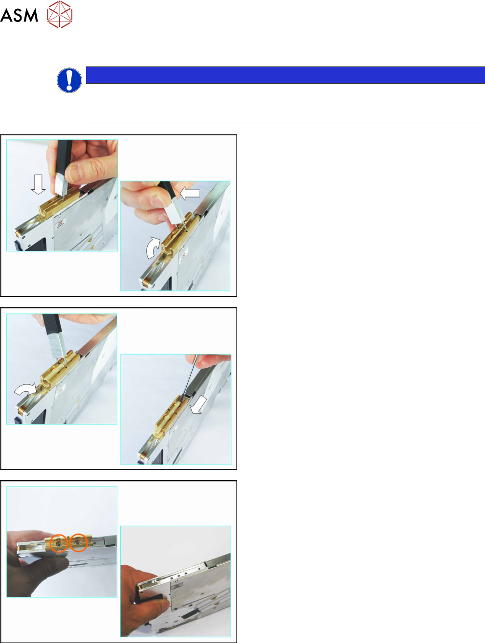
► Turn the feeder module so that its underside is at
the top.
► Place the sliding foil remover into the sliding
guide, as shown in the diagram.
► Lever the sliding foil out of the engaged position.
► Lever the sliding foil until it has been turned by
approximately90°.
► Push the sliding foil towards the front and out of
the sliding guide.
► Loosen the 2 screws.
► Lift the sliding guide off the feeder module.
6 Repairing the X Feeder modules
6.2 Rear Sliding Guide
Service Manual SIPLACE X-Feeder 4 - 88 mm 11/2017 21
6.1.2 Fitting the Front Sliding Guide
NOTICE
The pickup window must be fitted
To prevent damage to the sprocket wheel and the reject device, make sure that the pickup
window is fitted for this work.
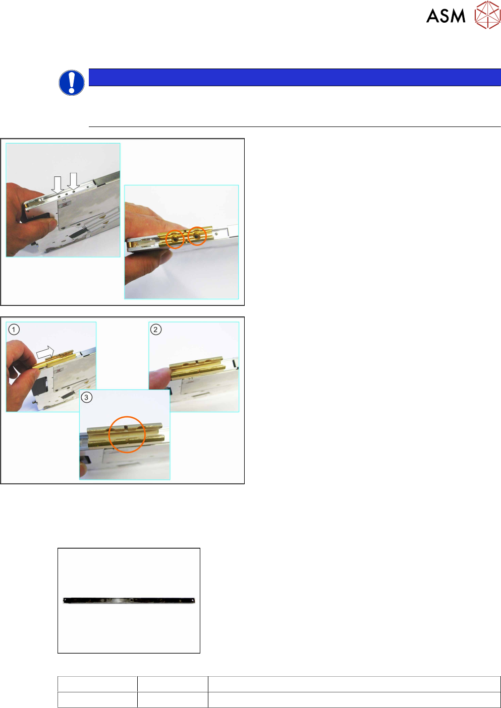
► Insert the sliding guide - as shown in the diagram
- into the groove on the drive carrier.
► Position the front sliding guide so that you can
see the holes for the screws through the sliding
guide.
► Fix the sliding guide to the feeder module with
the 2 Phillips head screws (M3x10mm).
► Press the sliding foil slightly together.
► Push the sliding foil from the front into the sliding
guide, until it engages audibly.
6.2 Rear Sliding Guide
Required spare parts
Fig.2: Rear sliding guide L200
Feeder module Item no. Designation
4–88mm 03003994-Sxx Sliding guide/rear L200
Required tools
●
Phillips screwdriver
●
TORX screwdriver size T8
6 Repairing the X Feeder modules
6.2 Rear Sliding Guide
22 Service Manual SIPLACE X-Feeder 4 - 88 mm 11/2017
6.2.1 Removing the Rear Sliding Guide
NOTICE
The pickup window must be fitted
To prevent damage to the sprocket wheel and the reject device, make sure that the pickup
window is fitted for this work.
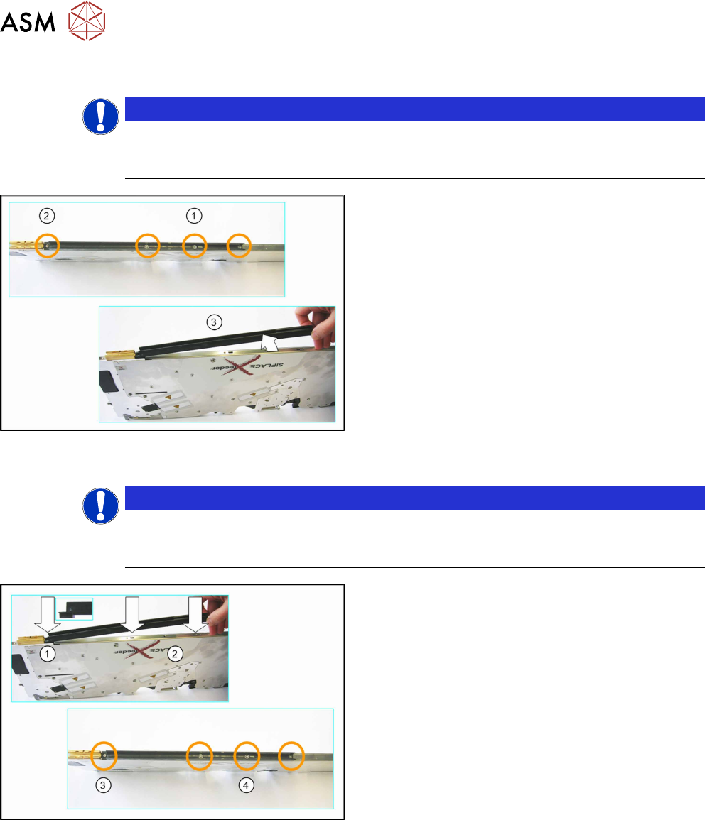
► Loosen the 3 rear screws on the sliding guide. (1)
► Loosen the front screw on the sliding guide. (2)
► Lift the sliding guide up at the back and pull up-
wards and off.
6.2.2 Fitting the Rear Sliding Guide
NOTICE
The pickup window must be fitted
To prevent damage to the sprocket wheel and the reject device, make sure that the pickup
window is fitted for this work.
► Fit the sliding guide – as shown in the diagram –
to the underside of the feeder module.
(1) Push the left part of the rear sliding guide (as
shown in the diagram) as far left as the stop, to-
wards the front sliding guide and into the recess.
(2) Then lower the two snap tabs of the sliding
guide into the openings provided on the under-
side of the feeder module.
► (3) Screw the sliding guide to the feeder module
at the front with the cylinder head screw
(2.5x8mm) and spring circlip.
Note:
When using feeder modules with a width of 4-
12mm, use the mushroom head cutting screws
(T82.5x10mm).
For feeder modules of 16mm width and above,
use cylinder head screws (2.5 x 8mm).
► (4) Screw the sliding guide onto the back of the
feeder module.