00196602-05_SM_SIPLACE_X-Feeder_EN.pdf - 第81页
6 Repairing the X Feeder modules 6.7 Operating Panel Assembly Service Manual SIPLACE X-Feeder 4 - 88 mm 11/2017 81 6.7.5 Removing the Operating Panel (16 - 88 mm) ► Carefully place the feeder module down on its left side…

6 Repairing the X Feeder modules
6.7 Operating Panel Assembly
80 Service Manual SIPLACE X-Feeder 4 - 88 mm 11/2017
► (1) Insert the flat ribbon cable into the connection,
as far as the stop.
Make sure that the blue surface at the end of the
cable is at the top and that the flat ribbon cable
lies straight in the connection.
► Swing the lock on the connection down onto the
flat ribbon cable.
Make sure that the flat ribbon cable is fitted firmly
in the connection. Tug gently on the cable to
check.
► Check again whether the flat ribbon cable is fitted
straight in the connection.
If necessary, open the lock and correct the posi-
tion of the cable before closing the lock again.
► (2) Carefully insert the connector in the direction
of the arrow, as far as the stop, into the connec-
tion shown.
Make sure that the smooth side of the connector
is at the top.
CAUTION!
Do not push the connector with force into the
connection, otherwise individual pins may
break off or be distorted.
.
► Fit the left side cover into place (see 6.3.2 "Fitting
the Left Side Cover" [}24]).
► Carefully place the feeder module down on its left
side.
► Fasten the 2 self-cutting Torx screws marked in
the diagram.
6 Repairing the X Feeder modules
6.7 Operating Panel Assembly
Service Manual SIPLACE X-Feeder 4 - 88 mm 11/2017 81
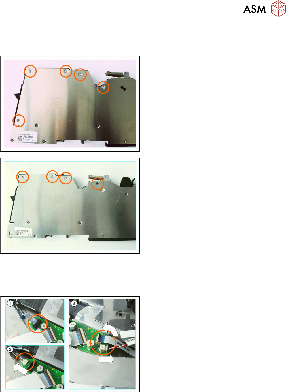
6.7.5 Removing the Operating Panel (16 - 88 mm)
► Carefully place the feeder module down on its left side.
► Remove the screws shown in the following diagram.
Example diagram for X feeder modules with 16mm
width
Example diagram for X feeder modules with 24 -
88mm width
► Now carefully place the feeder module down on its right-hand side.
► Remove the left side cover (see 6.3.1 "Removing the Left Side Cover" [}23]).
► (1) Pull the connector marked in the diagram up
and out of its connection.
To loosen the connector, move it carefully from
side to side.
► (2) Pull the connector marked in the diagram out
of its connection in the direction of the arrow. Pull
on the connector and NOT on the cable.
► (3) Carefully swing the lock on the flat ribbon
cable connection up to the left and release the
flat ribbon cable.
Make sure that the lock is not pushed too far
back. It could break off if you do this.
► Pull the connector shown in the diagram out of its
connection in the direction of the arrow. Pull on
the connector and NOT on the cable.
6 Repairing the X Feeder modules
6.7 Operating Panel Assembly
82 Service Manual SIPLACE X-Feeder 4 - 88 mm 11/2017
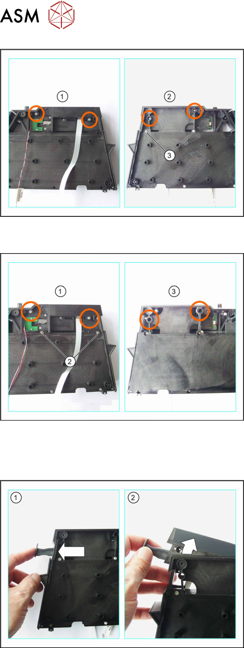
For 16-24mm feeder modules only
► Lift the foil disposal, together with the foil con-
tainer, out of the feeder module.
► Remove the two screws shown in the left-hand
diagram (1).
► Turn the foil disposal drive over, together with the
foil container.
► Remove the two screws shown in the right-hand
diagram (2).
► Loosen the marked screws (3), so that the oper-
ating panel can be moved. One complete rotation
should be sufficient.
If you are still unable to move the operating
panel, loosen the two screws by a further rota-
tion.
For 32-88mm feeder modules only
► Lift the foil disposal, together with the foil con-
tainer, out of the feeder module.
► Remove the two screws shown in the left-hand
diagram (1).
► Loosen the marked screws (2), so that the oper-
ating panel can be moved. One complete rotation
should be sufficient.
If you are still unable to move the operating
panel, loosen the two screws by a further rota-
tion.
► Turn the foil disposal drive over, together with the
foil container.
► Remove the two screws shown in the right-hand
diagram (3).
When using wider feeder modules, you need a
longer Torx screwdriver size 8.
► Turn the foil disposal drive over, together with the
foil container.
► (1) Press the removal handle so that this springs
out.
► (2) Lift the operating panel up and out of the foil
container frame.