00196602-05_SM_SIPLACE_X-Feeder_EN.pdf - 第33页
6 Repairing the X Feeder modules 6.4 Tape Drive Service Manual SIPLACE X-Feeder 4 - 88 mm 11/2017 33 6.4.2.3 Removing the Splice Sensor (16 - 88 mm) ► Remove the left side cover (see 6.3.1 "Removing the Left Side Co…
6 Repairing the X Feeder modules
6.4 Tape Drive
32 Service Manual SIPLACE X-Feeder 4 - 88 mm 11/2017
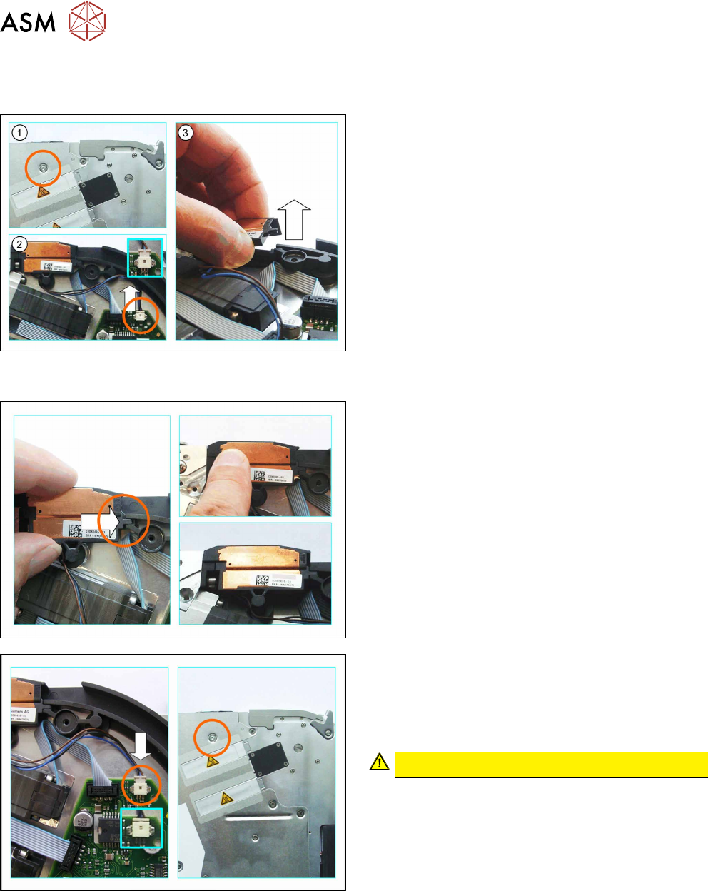
6.4.2.1 Removing the Splice Sensor (8 - 12 mm)
► Remove the left side cover (see 6.3.1 "Removing the Left Side Cover" [}23]).
► (1) Loosen the screw on the right side cover, as
marked in the diagram.
► (2) Carefully push the connector up and out of
the connection marked in the diagram, using a
small slotted screwdriver or similar tool.
Push the connector and do NOT pull on the
cable.
► Lift the splice sensor up and out of the holding
device.
6.4.2.2 Fitting the Splice Sensor (8 - 12 mm)
► Push the splice sensor from the left, with the
snap tab, as far as the stop in the holding device
on the tape duct.
► Press the splice sensor on the left side, down into
the recess next to the tape drive.
► Make sure that the smooth side of the connector
is at the top.
► Carefully insert the connector as far as the stop,
into the connection on the board, as marked in
the diagram.
CAUTION!
Do not push the connector with force into the
connection, otherwise individual pins may break
off or be distorted.
.
► Fix the splice sensor to the right side cover with
the mushroom head cutting screw (T2.5x6mm).
► Fit the left side cover into place (see section 6.3.2 "Fitting the Left Side Cover" [}24]).
► Fit the rear slide bearing (see 6.2.2 "Fitting the Rear Sliding Guide" [}22]).
6 Repairing the X Feeder modules
6.4 Tape Drive
Service Manual SIPLACE X-Feeder 4 - 88 mm 11/2017 33
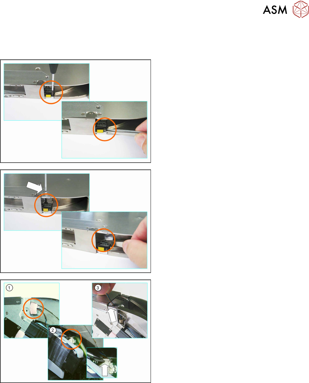
6.4.2.3 Removing the Splice Sensor (16 - 88 mm)
► Remove the left side cover (see 6.3.1 "Removing the Left Side Cover" [}23]).
► Carefully place the feeder module down on its left side.
► Loosen the screw marked in the diagram.
► Remove the screw e.g. with a pair of tweezers.
► Insert the Phillips screwdriver through the marked
opening in the side cover.
► Loosen the back screw marked in the diagram.
► Remove the screw e.g. with a pair of tweezers.
► Carefully place the feeder module on its right
side.
► (1) Loosen the foam rubber which closes the
opening to the tape duct.
► (2) Unplug the splice sensor connector from the
connection on the board.
Use a small slotted screwdriver or similar tool to
help you.
Push the connector up and out of the connection
(see small diagram).
Do NOT pull on the cable.
► (3) Remove the splice sensor from the tape duct
and pull the cable and connector up and out of
the opening.
6 Repairing the X Feeder modules
6.4 Tape Drive
34 Service Manual SIPLACE X-Feeder 4 - 88 mm 11/2017
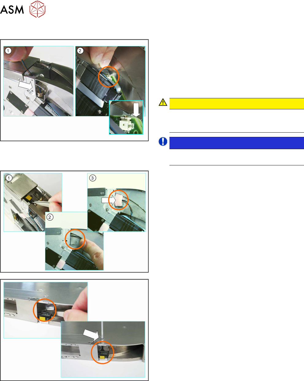
6.4.2.4 Fitting the Splice Sensor (16 - 88 mm)
► (1) Insert the splice sensor connector through the
opening in the tape duct.
► Make sure that the smooth side of the connector
is at the top.
► (2) Use a pair of tweezers or something similar to
carefully push the connector as far as the end
stop into the marked connection on the board.
CAUTION!
Do not push the connector with force into the
connection, otherwise individual pins may break
off or be distorted.
.
NOTICE!
Take great care when connecting the connector.
Take your time.
.
► (1) Position the splice sensor in the tape duct.
Gently tug on the splice sensor cable in the re-
cess on the feeder module side panel.
Make sure that none of the cable is in the tape
duct.
► (2) Run the cable as marked in the diagram.
► (3) Close the opening to the tape duct with the
foam rubber.
► Position the splice sensor in the tape duct.
► Hold the screw with a pair of tweezers in the rear
hole.
► Insert the Phillips screwdriver through the marked
opening in the side cover.
► Fasten the back screw marked in the diagram.