00196602-05_SM_SIPLACE_X-Feeder_EN.pdf - 第4页
4 Service Manual SIPLACE X-Feeder 4 - 88 mm 11/2017 Contents 6.4.3 Magnetic Shield (4mmX Only) .. 35 6.4.3.1 Removing the Magnetic Shield .. 35 6.4.3.2 Fitting the Magnetic Shield .. 36 6.5 Foil Disposal .. 37 …

3Service Manual SIPLACE X-Feeder 4 - 88 mm 11/2017
Contents
Contents
1 Introduction.. 5
1.1 Safety Instructions.. 5
1.1.1 Conventions for the Use of Safety Instructions and Symbols.. 5
1.2 Environmentally-Friendly Disposal of Materials and Components.. 6
1.3 Use of Original SIPLACE Accessories and Spare Parts.. 6
1.4 Information About This Service Manual.. 6
1.5 Release History.. 6
1.6 SIPLACE on the World Wide Web (WWW).. 6
1.7 Staff Qualifications and Training.. 7
2 General.. 9
2.1 Requirements.. 9
2.2 Warranty.. 9
2.3 Equipment Required.. 10
2.4 Safety Instructions.. 10
3 X-Feeder Test Station.. 11
3.1 X Feeder Test Station Error Messages.. 12
3.2 Rare Errors.. 14
4 X Feeder Verification System.. 15
5 Diagnosis and Solutions.. 17
5.1 Assignment of Symptoms/Repairs.. 17
6 Repairing the X Feeder modules.. 19
6.1 Front sliding guide.. 19
6.1.1 Removing the Front Sliding Guide.. 20
6.1.2 Fitting the Front Sliding Guide.. 21
6.2 Rear Sliding Guide.. 21
6.2.1 Removing the Rear Sliding Guide.. 22
6.2.2 Fitting the Rear Sliding Guide.. 22
6.3 Left Side Cover.. 23
6.3.1 Removing the Left Side Cover.. 23
6.3.2 Fitting the Left Side Cover.. 24
6.4 Tape Drive.. 27
6.4.1 Pickup Window.. 27
6.4.1.1 Removing the Pickup Window (4 - 12 mm).. 27
6.4.1.2 Fitting the Pickup Window (4 - 12 mm).. 28
6.4.1.3 Removing the Pickup Window (16 - 88 mm).. 30
6.4.1.4 Fitting the Pickup Window (16 - 88 mm).. 30
6.4.2 Splice Sensor.. 31
6.4.2.1 Removing the Splice Sensor (8 - 12 mm).. 32
6.4.2.2 Fitting the Splice Sensor (8 - 12 mm).. 32
6.4.2.3 Removing the Splice Sensor (16 - 88 mm).. 33
6.4.2.4 Fitting the Splice Sensor (16 - 88 mm).. 34

4 Service Manual SIPLACE X-Feeder 4 - 88 mm 11/2017
Contents
6.4.3 Magnetic Shield (4mmX Only).. 35
6.4.3.1 Removing the Magnetic Shield.. 35
6.4.3.2 Fitting the Magnetic Shield.. 36
6.5 Foil Disposal.. 37
6.5.1 Foil Disposal Drive Assembly.. 37
6.5.1.1 Removing the Foil Disposal Drive (4 - 12 mm).. 38
6.5.1.2 Fitting the Foil Disposal Drive (4 - 12 mm).. 39
6.5.1.3 Removing the Foil Disposal Drive (16 mm).. 40
6.5.1.4 Fitting the Foil Disposal Drive (16 mm).. 42
6.5.1.5 Removing the Foil Disposal Drive (24 - 88 mm).. 44
6.5.1.6 Fitting the Foil Disposal Drive (24 - 88 mm).. 46
6.5.2 Stripping Device Foil Disposal.. 49
6.5.2.1 Removing the Stripping Device (4 mm).. 49
6.5.2.2 Fitting the Stripping Device (4 mm).. 50
6.5.2.3 Removing the Stripping Device (8-88mm).. 50
6.5.2.4 Fitting the Stripping Device (8–88mm).. 50
6.5.3 Knurled Tamp Wheel.. 51
6.5.3.1 Removing the Knurled Tamp Wheel (4 - 88 mm).. 52
6.5.3.2 Fitting the Knurled Tamp Wheel (4 - 88 mm).. 52
6.5.4 Foil Rocker.. 53
6.5.4.1 Removing the Foil Rocker (4 - 88 mm).. 54
6.5.4.2 Fitting the Foil Rocker 4 - 88 mm).. 55
6.5.5 Ratchet.. 56
6.5.5.1 Removing the Ratchet (4 - 12 mm).. 56
6.5.5.2 Fitting the Ratchet (4 - 12 mm).. 58
6.5.5.3 Removing the Ratchet (16 - 88 mm).. 59
6.5.5.4 Fitting the Ratchet (16 - 88 mm).. 61
6.5.6 Tape Disposal Flap.. 65
6.5.6.1 Removing the Flap (4–12mm).. 65
6.5.6.2 Fitting the Flap (4–12mm).. 66
6.5.6.3 Removing the Flap (16–88mm).. 66
6.5.6.4 Fitting the Flap (16–88mm).. 66
6.6 Rocker.. 67
6.6.1 Rocker Stripping Device (4mm only).. 67
6.6.1.1 Removing the Rocker Stripping Device.. 67
6.6.1.2 Fitting the Rocker Stripping Device.. 68
6.6.2 Rocker Assembly.. 68
6.6.2.1 Removing the Rocker (4 - 88 mm).. 69
6.6.2.2 Fitting the Rocker (4 - 88 mm).. 70
6.6.3 Tamp Wheel for Rocker.. 71
6.6.3.1 Removing the Tamp Wheel for the Rocker (4 - 88 mm).. 72
6.6.3.2 Fitting the Tamp Wheel for the Rocker (4 - 16 mm).. 72
6.6.3.3 Fitting the Tamp Wheel for the Rocker (24 - 88 mm).. 72
6.6.4 Bearing Shaft.. 73
6.7 Operating Panel Assembly.. 74
6.7.1 Removing the Operating Panel (4+8 mm).. 74
6.7.2 Fitting the Operating Panel (4+8mm).. 75
6.7.3 Removing the Operating Panel (12 mm).. 76
6.7.4 Fitting the Operating Panel (12 mm).. 78
6.7.5 Removing the Operating Panel (16 - 88 mm).. 81
6.7.6 Fitting the Operating Panel (16 - 88 mm).. 83
6.8 Leaf Spring.. 87
6.8.1 Removing/Fitting the Leaf Spring (4 - 12 mm).. 87
6.8.2 Removing/Fitting the Leaf Spring (16 - 88 mm).. 88
1 Introduction
1.1 Safety Instructions
Service Manual SIPLACE X-Feeder 4 - 88 mm 11/2017 5
1 Introduction
This manual describes service work performed on the SIPLACE® 4-88 mm X feeder modules.
1.1 Safety Instructions
DANGER
Nonobservance of these safety instructions may cause injury to personnel and dam-
age to the machine!
► Please observe the safety instructions in the user manual of the relevant machine
for all work!
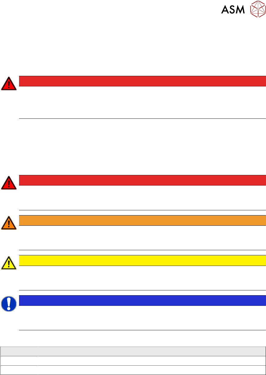
1.1.1 Conventions for the Use of Safety Instructions and Symbols
Safety Instructions
This manual contains notes that must be observed to guarantee your personal safety and to avoid
damage to equipment. These notes are highlighted by warning triangles and are indicated as fol-
lows according to the level of risk:
DANGER
Definition
For the purposes of this manual, this indicates that fatal or severe injuries or considerable
damage to property will occur if this hazard warning is not observed.
WARNING
Definition
For the purposes of this manual, this indicates that fatal or severe injuries or considerable
damage to equipment may occur if these warning instructions are not followed.
CAUTION
Definition
For the purposes of this manual, this indicates that minor injuries or damage to property
may occur if this caution is not observed.
NOTICE
Definition
For the purposes of this manual, this note provides information about the product or indic-
ates a part of the manual that requires particular attention.
Symbols
Example Description
Next This typeface marks controls and interface elements in the software.
► These symbols indicate actions that have to be performed by the operator.