00196602-05_SM_SIPLACE_X-Feeder_EN.pdf - 第57页
6 Repairing the X Feeder modules 6.5 Foil Disposal Service Manual SIPLACE X-Feeder 4 - 88 mm 11/2017 57 ► Loosen the screws shown in the left-hand dia- gram. ► Lift the cover plate off the foil disposal drive. ► Remove t…
6 Repairing the X Feeder modules
6.5 Foil Disposal
56 Service Manual SIPLACE X-Feeder 4 - 88 mm 11/2017
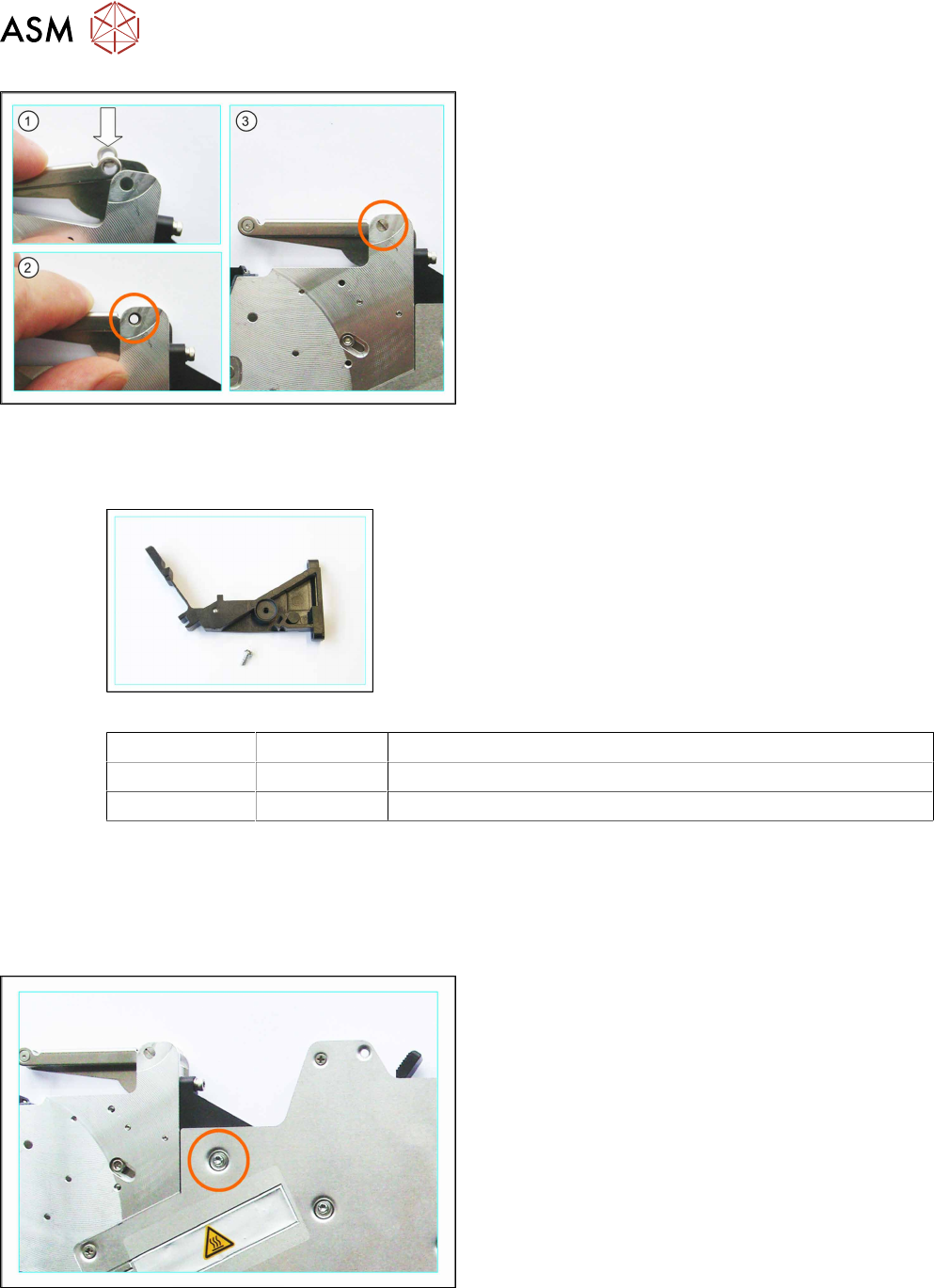
► (1) Correctly insert the roller into the foil rocker,
so that you can see through the roller.
► (2) Position the foil rocker and roller so that you
can see through the holding device on the foil
drive.
► (3) Insert the bearing shaft into the opening and
fix the foil rocker with it to the foil disposal drive.
6.5.5 Ratchet
Required spare parts
Example: ratchet 8mm
Feeder module Item no. Designation
4, 8+16mm 03010342-Sxx Ratchet assembly,/rollers X8
12, 24- 88mm 03010354-Sxx Ratchet assembly/rollers X12
Required tools
●
Phillips screwdriver
●
Hexagon socket-head screwdriver size 2
6.5.5.1 Removing the Ratchet (4 - 12 mm)
► Carefully place the feeder module down on its left
side.
► Loosen the screw marked in the diagram.
► Now carefully place the feeder module down on
its right-hand side.
► Remove the left side cover (see 6.3.1 "Removing
the Left Side Cover" [}23]).
6 Repairing the X Feeder modules
6.5 Foil Disposal
Service Manual SIPLACE X-Feeder 4 - 88 mm 11/2017 57
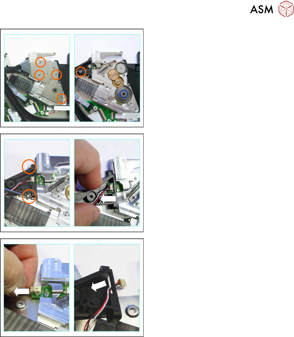
► Loosen the screws shown in the left-hand dia-
gram.
► Lift the cover plate off the foil disposal drive.
► Remove the rubber seal marked in the right-hand
diagram.
► Loosen the two screws marked in the diagram.
► Carefully pull the ratchet to the left, away from
the foil disposal drive.
► Carefully pull the connector to the left and out of
the connection marked in the diagram.
Pull on the connector and NOT on the cable.
► Remove the cable from the opening in the
ratchet.
The ratchet is now free.
6 Repairing the X Feeder modules
6.5 Foil Disposal
58 Service Manual SIPLACE X-Feeder 4 - 88 mm 11/2017
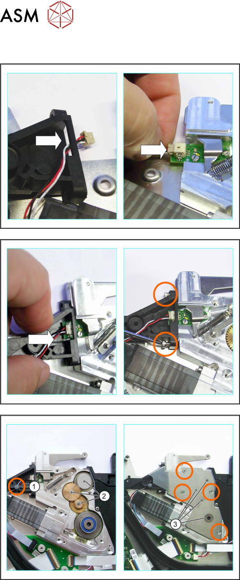
6.5.5.2 Fitting the Ratchet (4 - 12 mm)
► Insert the connector through the opening in the
ratchet.
► Plug the connector into the connection shown in
the diagram.
Make sure that the smooth side of the connector
is at the top.
► Push the ratchet sideways under the small board,
as far as the foil disposal drive.
Make sure that the left side of the ratchet is
against the tape duct.
► Fix the ratchet first with the top cylinder head
screw (2.5x10mm).
Do not tighten the screw fully as you still need to
move the ratchet slightly.
► Fix the ratchet into place with the bottom cylinder
head screw (2.5x10mm).
► Now tighten the top screw.
► Run the cable as marked in the diagram.
► Fix the cable with the rubber seal.
Make sure that the rubber seal does not project
beyond the holder.
► Make sure that the corresponding washers are
on the toothed wheel axes (2).
► Place the cover plate onto the foil disposal drive.
Make sure that the cover plate engages at the
toothed wheel axes (3).
► Fix the cover plate with the countersunk screws
marked in the diagram (M2.5 x 5mm).
► Then fit the left side cover into place (see 6.3.2
"Fitting the Left Side Cover" [}24]).