00196602-05_SM_SIPLACE_X-Feeder_EN.pdf - 第24页
6 Repairing the X Feeder modules 6.3 Left Side Cover 24 Service Manual SIPLACE X-Feeder 4 - 88 mm 11/2017 ► Lift the back of the side cover. ► Pull the side cover at a slight angle towards the back. Make sure that you pu…
6 Repairing the X Feeder modules
6.3 Left Side Cover
Service Manual SIPLACE X-Feeder 4 - 88 mm 11/2017 23
6.3 Left Side Cover
CAUTION
Observe the ESD regulations!
Pay attention to feeder module ESD safety:
Before you open the side cover, make sure you are wearing the ESD protection wristband,
to prevent damage to the highly sensitive boards inside the feeder module.
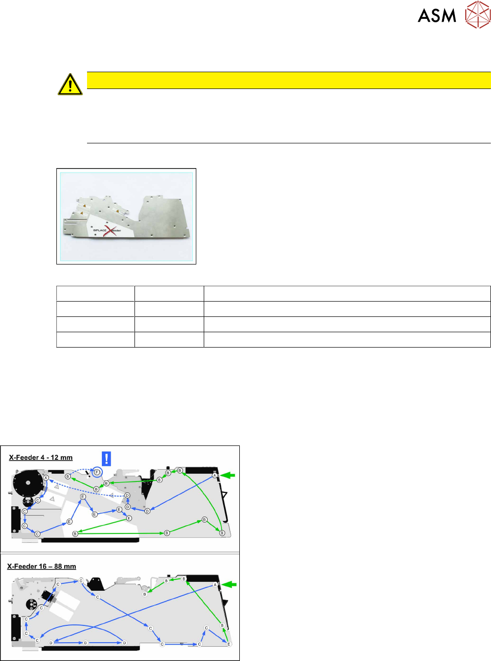
Required spare parts
Example: side cover on left 4-12mm
Feeder module Item no. Designation
4+ 8mm 03052072-Sxx Cover assembly on left feeder side, /X8
12 mm 03021934-Sxx Cover /left feeder side X12
16–88mm 03021215-Sxx Cover /left feeder side X16 - 88
Required tools
●
Phillips screwdriver 0.9Nm
●
TORX screwdriver 0.6Nm, size T8
●
Small Phillips screwdriver
6.3.1 Removing the Left Side Cover
► Only for 4–12mm feeder modules:
Remove the back sliding guide (see 6.2.1 "Re-
moving the Rear Sliding Guide" [}22]).
► Carefully place the feeder module with the right-
side side down on a stable, level and clean sur-
face.
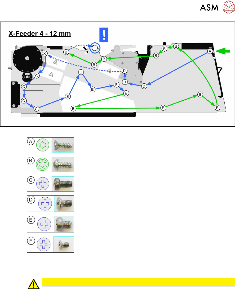
► Loosen the screws as shown in the diagram.
Green arrows point to the screws for which you need a
TORX screwdriver with a torque of 0.6Nm.
Blue arrows point to the screws for which you need a
Phillips screwdriver with a torque of 0.9Nm.
Start to loosen the screws at the position shown by the
green arrow.
For greater clarity, we recommend that you loosen the
same types of screws together and then keep them in
small, marked bowls.
6 Repairing the X Feeder modules
6.3 Left Side Cover
24 Service Manual SIPLACE X-Feeder 4 - 88 mm 11/2017
► Lift the back of the side cover.
► Pull the side cover at a slight angle towards the
back.
Make sure that you pull the lug straight out of the
drive unit.
► Place the side cover down on a clean, safe sur-
face.
6.3.2 Fitting the Left Side Cover
► Carefully place the feeder module with the right-
side side down on a stable, level and clean sur-
face.
► (1) Lift the side cover onto the feeder module at a
slant and from the right-hand side.
(2) Make sure that the lugs insert into the drive
unit.
► (3) Make sure that the side cover is aligned with
the operating panel.
► Screw the side cover onto the feeder module, as shown in the following diagrams.
Start with screw (A) on the right, under the operating panel.
Green arrows point to the screws for which you need a TORX screwdriver with a torque of 0.6Nm.
Blue arrows point to the screws for which you need a Phillips screwdriver with a torque of 0.9Nm.
CAUTION
Do not distort the screws
When you tighten the screws, make sure that these are NOT distorted.
6 Repairing the X Feeder modules
6.3 Left Side Cover
Service Manual SIPLACE X-Feeder 4 - 88 mm 11/2017 25
Designation Size Torque Quantity
RF-SN85 2.5 x 7.5 mm 0.6 Nm 1
RF-SN75 2.5 x 6 mm 0.6 Nm 10
SN213307 M2.5x5mm 0.9 Nm 5 (4+8mm)
4 (12mm)
DIN965 M2.5x5mm 0.9 Nm 3
SN213307 M2.5x3mm 0.9 Nm 5
RF-SN75 2.5 x 6 mm - 1
(X) The screw (X) varies between the different feeder modules.
In 4 - 8mm feeder modules, this is a screw of type (D).
In 12mm feeder modules, this is a screw of type (C).
CAUTION
The screw marked F is easily damaged
Tighten the screw marked (F) carefully with a small Phillips screwdriver.
Make sure that this screw is NOT distorted.