User Manual E-by-SIPLACE 用户手册.pdf - 第115页
User manual E by SIPLACE 3 Technical data and assemblies From software version SC 712.1 Edition 05/2019 3.4 Overviews of the modules 115 3.4 Overviews of the modules 3.4.1 Overview of E by SIPL ACE double sided assemblie…
3 Technical data and assemblies User manual E by SIPLACE
3.3 Dimensions and weight From software version SC 712.1 Edition 05/2019
114
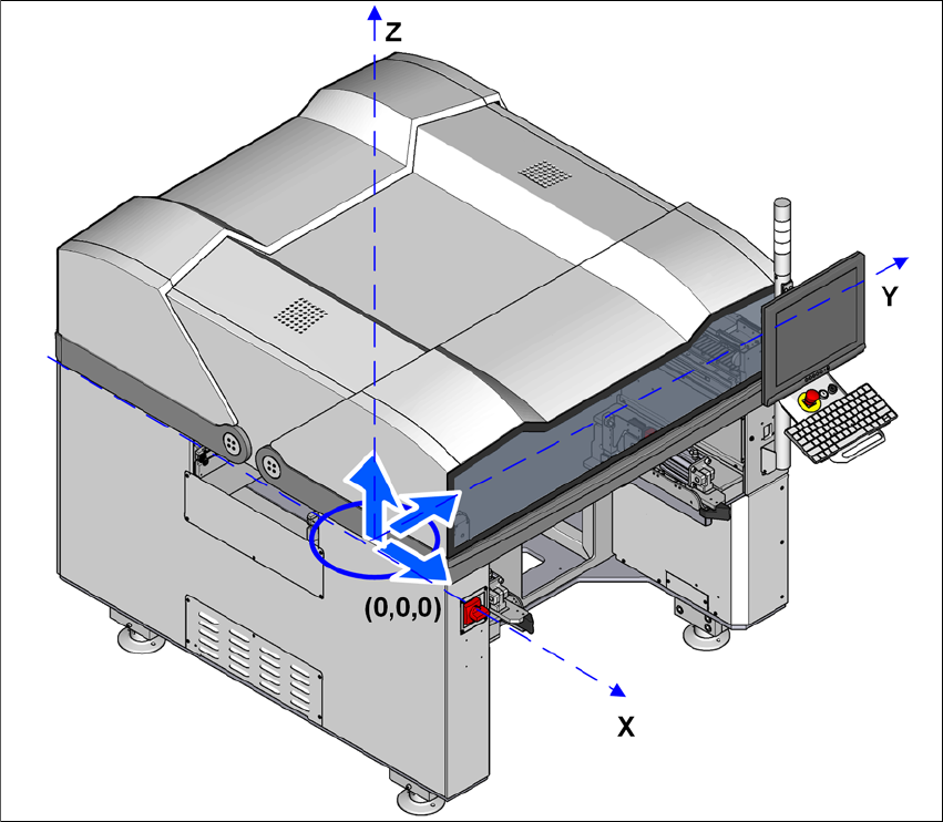
3.3.5 Center of gravity
3.3.5.1 Machine center of gravity
3
Fig. 3.3 - 8 Center of gravity for E by SIPLACE machines in millimeters
X coordinate 0 mm
Y coordinate 0 mm
Z coordinate 721 mm
These center of gravity coordinates relate to placement machines with a PCB conveyor height of
900 mm.
User manual E by SIPLACE 3 Technical data and assemblies
From software version SC 712.1 Edition 05/2019 3.4 Overviews of the modules
115
3.4 Overviews of the modules
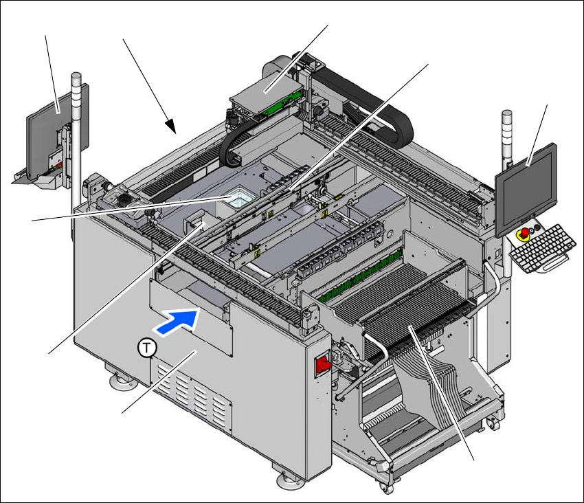
3.4.1 Overview of E by SIPLACE double sided assemblies
3
3
Fig. 3.4 - 1 E by SIPLACE double sided machine - overview of assemblies
(1) Basic module
(2) Reject bin
(3) Stationary cameras (optional)
(4) Monitor with keyboard (2x) on location 2 (optional)
(5) Location 2 with COT insert, tape cutter, empty tape duct
(6) Gantry with placement head (according to the configuration)
(7) PCB conveyor (single conveyor)
(8) Monitor with keyboard (2x) at location 1
(9) Changeover table at location 1
(T) Direction of PCB transport
(1)
(6)
(7)
(8)
(9)
(4)
(5)
(3)
(2)
3 Technical data and assemblies User manual E by SIPLACE
3.4 Overviews of the modules From software version SC 712.1 Edition 05/2019
116
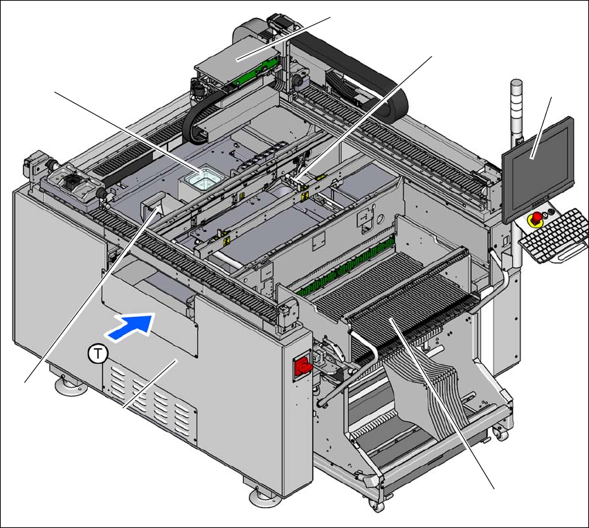
3.4.2 Overview of E by SIPLACE single sided assemblies
3
3
Fig. 3.4 - 2 E by SIPLACE single sided machine - overview of assemblies
(1) Basic module
(2) Reject bin
(3) Stationary cameras (optional)
(4) Gantry with placement head (according to the configuration)
(5) PCB conveyor (single conveyor)
(6) Monitor with keyboard at location 1
(7) Changeover table at location 1
(T) Direction of PCB transport
(1)
(4)
(5)
(6)
(7)
(2)
(3)