User Manual E-by-SIPLACE 用户手册.pdf - 第87页
User manual E by SIPLACE 2 Operational safety From software version SC 712.1 Edition 05/2019 2.7 Safety featur es 87 2 Fig. 2.7 - 6 EMERGENCY STOP loop for E by SIPLACE Start button pressed No No Yes No No Yes Yes 2 Acti…
2 Operational safety User manual E by SIPLACE
2.7 Safety features From software version SC 712.1 Edition 05/2019
86
There are three conditions that must be fulfilled in order to activate the safety contactors:
– The "software release" or "Control ON" signal must be issued.
– The EMERGENCY STOP loop must be closed.
– The start button must have been pressed.
2.7.4 EMERGENCY STOP loops and signaling circuit
2.7.4.1 EMERGENCY STOP loop structure
The following contacts are connected in series and form the EMERGENCY STOP loop:
– Make contact elements for the two protective cover switches
– Normally open (NO) contacts for the two EMERGENCY STOP buttons
– Make contact elements for the two changeover tables
2.7.4.2 Signaling circuit structure
The following modules in the signaling circuit are queried individually:
– The protective cover switches
– Signaling contacts on the changeover table
– EMERGENCY STOP button
All the signaling contacts are closed when the machine is on standby. If a protective cover, for
example, is lifted up, the associated signaling contact opens. This change of state is signaled to
the control computer via the CAN bus. An error message to this effect appears on the user inter-
face.
2.7.4.3 Description of the functions of the EMERGENCY STOP loops
The following conditions must be fulfilled in order to start and operate the machine:
– All changeover tables must be docked in and connected.
– All protective covers must be closed.
– Both emergency stop buttons must be released.
– The minimum operating pressure must have been reached.
– The software release ("Control ON") must be enabled, so that the start signal from the
"Start" button can activate the safety relay and safety units.
If one of the start buttons is now pressed, the safety contactors will be switched-on and the
machine is ready to use.
User manual E by SIPLACE 2 Operational safety
From software version SC 712.1 Edition 05/2019 2.7 Safety features
87
2
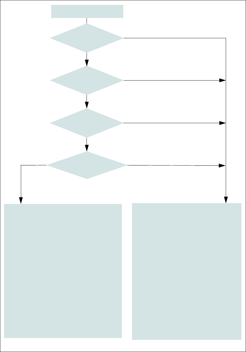
Fig. 2.7 - 6 EMERGENCY STOP loop for E by SIPLACE
Start button pressed
No
No
Yes
No
No
Yes
Yes
2
Active
Safety contactors No
Voltage
Y axis 0 V-
X axis 0 V-
Star axis 0 V-
DP axis 42 V-
Z axis (CP) 42 V-
Z axis (TH) 42 V-
Active
PCB conveyor No
Lifting table No
PCB clamping No
Width adjustment No
Tape cutter No
Changeover table feeding device Yes
Yes
Compressed
air min. 0.5 MPa
(5.0 bar)?
EMERGENCY STOP button
pressed?
- Protective cover open?
Changeover table
EMERGENCY STOP circuit
interrupted?
2
Active
Safety contactors Yes
Voltage
Y axis 300 V-
X axis 300 V-
Star axis 160 V-
DP axis 42 V-
Z axis (CP) 42 V-
Z axis (TH) 160 V-
Active
PCB conveyor Yes
Lifting table Yes
PCB clamping Yes
Width adjustment Yes
Tape cutter. Yes
Changeover table feeding device Yes
2 Operational safety User manual E by SIPLACE
2.7 Safety features From software version SC 712.1 Edition 05/2019
88
2.7.5 Hand guard (Dummy Feeder E)
2.7.5.1 Hand guard (Dummy Feeder E) at the locations
The hand guard is to be used when there is a gap in between feeders on the component table.
Slot the hand guard in the gap between feeders.
Push the hand guard until it touches the stop rail and the back of the feeder is in line with other
feeders.
2
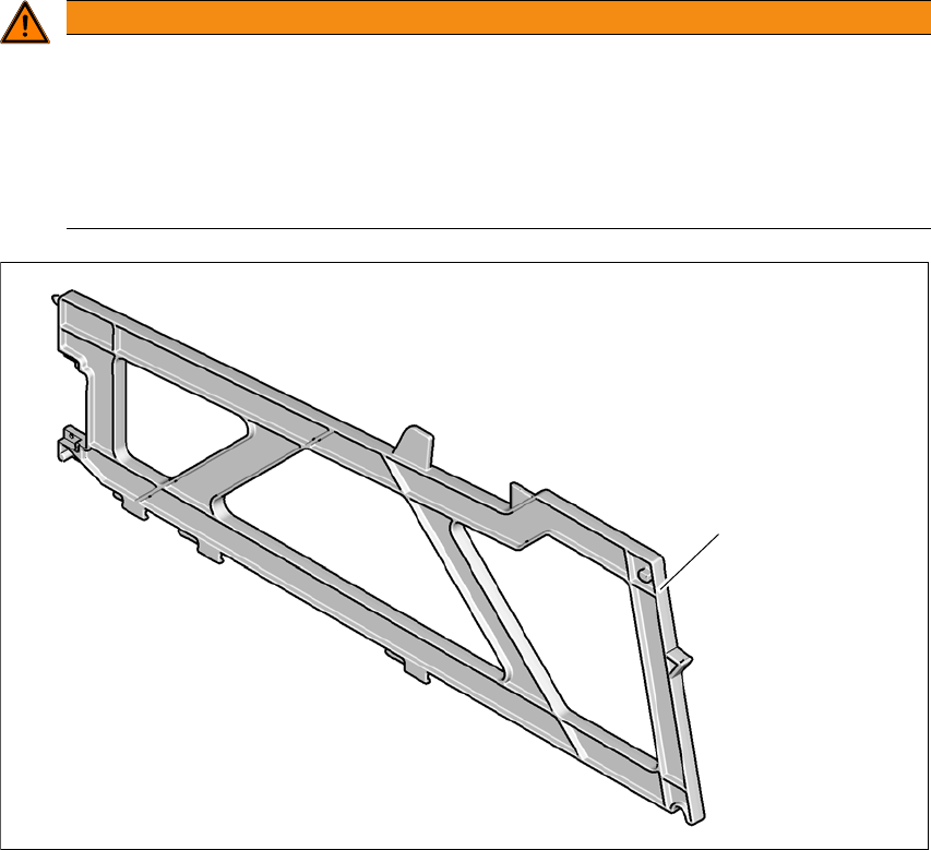
Fig. 2.7 - 7 Dummy feeder E on the table locations
(1) Dummy feeder E by SIPLACE, item no. 03113786-xx
WARNING
Operatio nal
Operational safety by occupying every second location!
The operational safety of the fixed table or changeover table in the E by SIPLACE is en-
sured if at least every second free location is occupied with a feeder module or hand guard
(dummy feeder).
Even when configuring manual tray carriers or a automatic tray changer, secure ev-
ery second location with a hand guard (dummy feeder).
(1)