User Manual E-by-SIPLACE 用户手册.pdf - 第130页
3 Technical data and assemblies User manual E by SIPLACE 3.5 Placement head From software version SC 712.1 Edition 05/201 9 130 3.5.4.1 Safety instructions 3 3 WARNING Please observe the w arning label section 2.2.6 , …
User manual E by SIPLACE 3 Technical data and assemblies
From software version SC 712.1 Edition 05/2019 3.5 Placement head
129
3.5.4 Vacuum pump
Each Collect&Place head (SIPLACE CP14/12/6) has its own vacuum generator, which supplies
the holding and placement circuit with the required vacuum. The vacuum generator for the place-
ment heads functions according to the Venturi principle. When operated together with a vacuum
pump, the Collect&Place head (SIPLACE CP14/12/6) reduce the compressed air consumption
considerably. The running costs will fall according to the energy costs incurred.
3
3
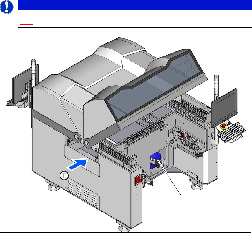
Fig. 3.5 - 7 Location of the vacuum pump
(1) Location of the vacuum pump
PLEASE NOTE
The compressed air consumption values with the vacuum pump can be found in section
3.2.4
, page 105.
(1)

3 Technical data and assemblies User manual E by SIPLACE
3.5 Placement head From software version SC 712.1 Edition 05/2019
130
3.5.4.1 Safety instructions
3
3
WARNING
Please observe the warning label section 2.2.6, page 61.
WARNING
Please observe the safety instructions of the vacuum pump in the user manual sup-
plied.
User manual E by SIPLACE 3 Technical data and assemblies
From software version SC 712.1 Edition 05/2019 3.5 Placement head
131
3.5.5 SIPLACE TH for high precision IC placement
Item no. 03033629-xx SIPLACE TH
Item no. 03112312-xx Stationary component camera, type 36 GigE
3
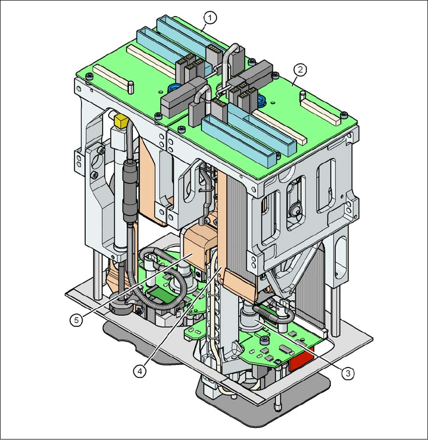
Fig. 3.5 - 8 SIPLACE TH for high precision IC placement
(1) Pick&Place module 1 (PP1) - the SIPLACE TH consists of 2 Pick&Place modules
(2) Pick&Place module 2 (PP2)
(3) DP axis
(4) Z axis drive
(5) Incremental distance measuring system for the Z axis