User Manual E-by-SIPLACE 用户手册.pdf - 第19页
User manual E by SIPLACE 1 Introduction From software version SC 712.1 Edition 05/2 019 1.2 Double sided E by SIPLACE 19 The double sided E by SIPLACE p lacem ent machines demonstrate – High precision – Placement p erfor…
1 Introduction User manual E by SIPLACE
1.2 Double sided E by SIPLACE From software version SC 712.1 Edition 05/2019
18
1.2 Double sided E by SIPLACE
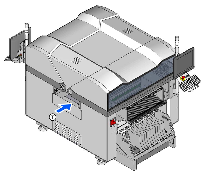
1.2.1 E by SIPLACE with fixed table
1
Fig. 1.2 - 1 Double sided E by SIPLACE placement machine with fixed table on location 1 (Example)
(T) Direction of PCB transport

User manual E by SIPLACE 1 Introduction
From software version SC 712.1 Edition 05/2019 1.2 Double sided E by SIPLACE
19
The double sided E by SIPLACE placement machines demonstrate
– High precision
– Placement performance up to the high end process range
– A wide ranging component range from 01005 components to a size of 200 mm x 110 mm.
Following placement methods are possible for processing the components:
– Collect&Place and
– Pick&Place
The E by SIPLACE placement machine consists one gantry. For an overview of the placement
head configuration, refer to section 3.1.1
from page 101.
These can be quickly and accurately positioned by linear motors, moving independently of one
another in the X and Y directions.
The E by SIPLACE machine supports the SIPLACE single conveyor.
There are two locations available for supplying components. One fixed table on location 1 and one
change over table on location 2 with 60 tracks.
Or 1
There are two locations available for supplying components. One fixed table on location 1 and one
fixed over table on location 2 with 60 tracks.
1 Introduction User manual E by SIPLACE
1.2 Double sided E by SIPLACE From software version SC 712.1 Edition 05/2019
20
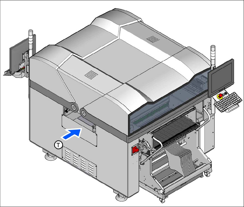
1.2.2 E by SIPLACE with change over table
1
Fig. 1.2 - 2 Double sided E by SIPLACE placement machine with change over table on location 1
(T) Direction of PCB transport