User Manual E-by-SIPLACE 用户手册.pdf - 第311页
User manual E by SIPLACE 6 Station extensions From software version SC 712.1 Edition 05/2 019 6.11 SIPLACE Comp onent Reject Conveyor E 311 6.11.1 General The SIPLACE Component Reject Co nveyor E is designed so that def …
6 Station extensions User manual E by SIPLACE
6.11 SIPLACE Component Reject Conveyor E From software version SC 712.1 Edition 05/2019
310
6.11 SIPLACE Component Reject Conveyor E
Item no. 03117077-xx SIPLACE Component Reject Conveyor E
6
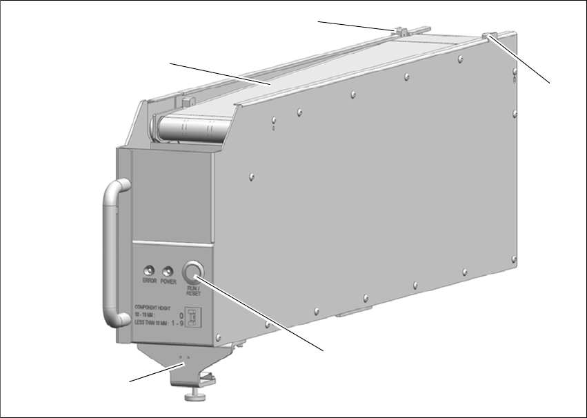
Fig. 6.11 - 1 SIPLACE Component Reject Conveyor E
(1) Belt Transfer
(2) Component Present Sensor
(3) RUN / RESET button
(4) Clamper
(3)
(2)
(1)
(2)
(4)
User manual E by SIPLACE 6 Station extensions
From software version SC 712.1 Edition 05/2019 6.11 SIPLACE Component Reject Conveyor E
311
6.11.1 General
The SIPLACE Component Reject Conveyor E is designed so that defective components (verified
by placement machine vision system) are placed onto conveyor belt and transferred out of ma-
chine for operator retrieval. It is handled like any other feeder for E by SIPLACE and can be
mounted onto its feeder tables.The purposes of Component Reject Conveyor are:
– Safely retrieve the reject component without opening / stopping machine.
– Store the rejected component on the conveyor belt, so that is not damaged and can still be
reused.
The SIPLACE Component Reject Conveyor E will be used on the changeover table for E by
SIPLACE. The same locating pin as E-series feeder is used in the SIPLACE Component Reject
Conveyor E to position it in place. In addition, a clamping mechanism is designed to fix it onto the
changeover table for E by SIPLACE. The SIPLACE Component Reject Conveyor E occupies 7
omega rail tracks and it can be placed anywhere on the table.
6.11.2 Description
Electrical power is provided to the SIPLACE Component Reject Conveyor E via Pogo pin connec-
tion. The placement machine places a defective component on the front end of the SIPLACE
Component Reject Conveyor E conveyor belt (Component Present Sensor, item 2 in fig. 6.11 - 1)
between detecting sensor. Once the Component Present Sensor is triggered, the belt will index
the component one pitch distance from placement point according to the set pitch length. After the
first component has been placed and moved out, the next reject component can be placed at
placement point without risk of component stacking.
At any time, the operator can press the RUN / RESET button (item 5 in fig. 6.11 - 1) and the belt
will run, transporting the components on the belt toward the rear of the SIPLACE Component Re-
ject Conveyor E. The operator can then remove components from the rear belt at any time without
opening the machine cover. Without any intervention, the conveyor continues to index each time
a component is placed on the belt. The lead component will eventually approach the end of the
conveyor, and trigger the rear sensor. The rear sensor will trigger an audible alarm to sound for
operator intervention. The alerted operator then removes components from the belt.
Even after the buzzer sounded, the conveyor is still functions normally; continue to index each
time a component is placed on the belt. If the operator does not intervene and manually clear the
rejected component from belt, the lead component will eventually fall off the end of belt and caught
by container at the end of the SIPLACE Component Reject Conveyor E. There is no direct com-
munication between SIPLACE Component Reject Conveyor E and the placement machine. The
placement machine does not know if the belt / rear container is full with rejected components.
6 Station extensions User manual E by SIPLACE
6.11 SIPLACE Component Reject Conveyor E From software version SC 712.1 Edition 05/2019
312
6.11.3 Technical data
– Dimension:
– Width 80mm
– Height 213.7 mm (excluding knurled knob, max height 17.5 mm at fully retracted)
– Length 611 mm
– Location on E by SIPLACE:
– Occupies 7 omega rail tracks and can be placed anywhere on the table, both Location 1
and Location 2
– Component sizes:
– Maximum weight: 100 gr
– Minimum Height: 1 mm
– Minimum Size: 3 x 1.4 mm
– Maximum Height: 19 mm
– Maximum Size: 60 x 60 mm
– Pitch Settings:
– Component height 10 - 19 mm ' Set to pitch 0 ' Conveyor will index 268 mm
– Component height less than 10 mm ' Set to pitch 1 - 9 ' Conveyor will index 10 - 100 mm,
to be selected depend on component's size.
– Communication
– Pogo-pin Interface
– Weight
– max 5.5 kg