User Manual E-by-SIPLACE 用户手册.pdf - 第149页
User manual E by SIPLACE 3 Technical data and assemblies From software version SC 712.1 Edition 05/2019 3.8 Feeder modules for E by SIPLACE 149 3.8.1.3 Manual removal of tantalum capacitors To prevent tantalum capacitors…

3 Technical data and assemblies User manual E by SIPLACE
3.8 Feeder modules for E by SIPLACE From software version SC 712.1 Edition 05/2019
148
3.8 Feeder modules for E by SIPLACE
Key properties of the SIPLACE SmartFeeder E include the high precision of the pickup position,
online programmability, a LED status displays and simple handling for feeder module changes
during the placement process. The power supply and the machine communication to the feeder
modules uses Pogo-pins.
3.8.1 Tape feeder modules
3.8.1.1 Tape material
The possible tape widths range from 8 mm to 56 mm. The tape material is blister or paper. The
design of the tape feeder modules was based on the following tape standards:
DIN EN 60286-3 (12/1998) / IEC 60286-3 (12/1997)
JIS C 0806-3 (1999)
ANSI/EIA 481-C (10/2003)
IEC 60286-3-2 3
The overall height of the blister tapes depends on the tape width, and must not exceed the follow-
ing maximum values:
For 8 mm paper tapes, the paper thickness must not exceed 1.6 mm.
3.8.1.2 Tape reel diameter
The tape reel diameter may be up to 19" (483 mm) for all feeder modules.
3
Tape width Overall height of the blister tapes
8 mm Max. 3.5 mm
12 mm Max. 16 mm
16 mm and wider Max. 16 mm
Tape reel diameter
with fixed table
with changeover table
up to 432 mm (17“)
up to 483 mm (19“)

User manual E by SIPLACE 3 Technical data and assemblies
From software version SC 712.1 Edition 05/2019 3.8 Feeder modules for E by SIPLACE
149
3.8.1.3 Manual removal of tantalum capacitors
To prevent tantalum capacitors which were not picked up from causing the tape material to burn
when it is cut, the user interface has been extended to include the option "Stop immediately on
pickup error". This option must be enabled in SIPLACE Pro. On the placement machine, the com-
ponent that was not picked up is paced forward again until it is ready for removal from the com-
ponent tape. The track is deactivated and the operator is sent an error message to remind him to
pick up the tantalum component from the tape. If an alternative track is available, the machine con-
tinues placing. The operator is able to stop the machine, however, and pick up the tantalum com-
ponent. If no alternative track is available and it is not possible to continue placement with other
components, the machine will stop. At this point, the operator can again remove the tantalum com-
ponent and acknowledge the error. Once the operator has restarted the machine, placement is
continued and components are picked up from the track that is now enabled once more.
3
PLEASE NOTE
This software function is also a good idea for expensive components.
Please observe the safety instructions for capacitors on metallic powder basis (see
section 2.5.3
, page 73).
3 Technical data and assemblies User manual E by SIPLACE
3.8 Feeder modules for E by SIPLACE From software version SC 712.1 Edition 05/2019
150
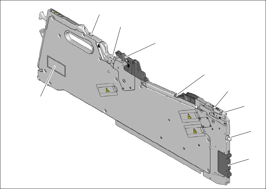
3.8.1.4 Design of the tape feeder modules
The two following diagrams show the design of the tape feeder module for the E by SIPLACE.
3
Fig. 3.8 - 1 SIPLACE SmartFeeder E - front view
(1) Pogo-pin interface
(2) "Front" centering pin
(3) Lever for raising the pick-up window in order to thread in and remove the component tape
(4) Pickup window
(5) Tape guide channel outlet
(6) Cover foil rocker
(7) Cover foil packing wheels
(8) Locking latch
(9) Typeplate
(1)
(2)
(3)
(4)
(5)
(6)
(7)
(8)
(9)