User Manual E-by-SIPLACE 用户手册.pdf - 第195页
User manual E by SIPLACE 4 Setting up and commissioning From software version SC 712.1 Edition 05/2019 4.4 Adjusting the changeover table to the PCB conveyor heig ht 195 4.4 Adjusting the changeover table to the PCB conv…
4 Setting up and commissioning User manual E by SIPLACE
4.3 Setting up the machine From software version SC 712.1 Edition 05/2019
194
Hit the feet with a hammer to check the load-bearing strength of the machine feet.
Use the spirit level to ensure that the machine is precisely aligned.
4.3.8 Removing the shipping braces
The shipping braces are attached to the linear guides. Each gantry is fastened with two shipping
braces on the X and Y axes.
Remove all the shipping braces from the gantry axes.
If the SIPLACE machine needs to be transported, always fit the shipping braces back onto
the conveyor.
4.3.9 Removing the corrosion protection from the guide rails
The machines were given a corrosion protection treatment before they were delivered.
4
4
CAUTION
Reduced product life of bearings and guide rails!
If the corrosion protection agent is mixed with the bearing grease on the axes this can
greatly reduce the service life of the bearings and guide rails.
You should therefore remove the corrosion protection from all the axes and bearings
when you traverse the machine axes for the first time during commissioning.
Grease all the axes and bearings with the grease described in the cleaning and
checking instructions.
CAUTION
Risk of damaging bearing grease!
Alcohol will damage the bearing grease in the guide carriages.
When cleaning the guide rails and scales, make sure that alcohol does not get into
the guide trolley.
User manual E by SIPLACE 4 Setting up and commissioning
From software version SC 712.1 Edition 05/2019 4.4 Adjusting the changeover table to the PCB conveyor height
195
4.4 Adjusting the changeover table to the PCB conveyor
height
The changeover table can be easily and quickly adjusted to the following PCB conveyor heights:
900 mm and 930 mm 4
950 mm (Option) 4
4
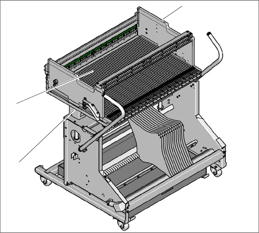
Fig. 4.4 - 1 Changeover table 60
(1) Holes for the transport heights of 900, 930 and 950 mm (behind the cover).
(2) Changeover table
(1)
(2)
(3)
4 Setting up and commissioning User manual E by SIPLACE
4.4 Adjusting the changeover table to the PCB conveyor height From software version SC 712.1 Edition 05/2019
196
4.4.1 Warning instructions
4
4.4.2 Tools and equipment
4
4.4.3 Changing the changeover table height
4
4
Loosen the fastening screws and lift the changeover table into the required position.
Fit and tighten the fastening screws.
WARNING
Adjustment of changeover table height by qualified persons!
Only qualified personnel are permitted to adjust the changeover table height.
Always follow the applicable accident prevention regulations.
Remove all the feeder modules from the changeover table, if you want to adjust the
height of the changeover table.
4
4
4
Heavy weight of the change over table!
The heavy weight of the change over table (88 kg) could cause
injuries if the change over table is not handled correctly.
Do not lift the change over table alone.
Use lifting aids and proper lifting techniques when lifting the
change over table.
You might need help of two additional persons when lifting
the change over table without lifting aids.
WARNING
Risk of damage!
Lifting and lowering the changeover table can lead to deformation of it.
Remove all the feeder modules from the changeover table.
Fit the lifting aids to the changeover table in order to adjust the height.
WARNING
Risk of hand crushing!
Lifting and lowering the changeover table can crushing the hands.
Take care when lifting and lowering the changeover table.