User Manual E-by-SIPLACE 用户手册.pdf - 第92页
2 Operational safety User manual E by SIPLACE 2.8 Residual voltages and discharge times in the machine From so ftware version SC 712.1 Edition 05/2019 92 2.8.1.2 Machine switched off at the main power switch and discon n…
User manual E by SIPLACE 2 Operational safety
From software version SC 712.1 Edition 05/2019 2.8 Residual voltages and discharge times in the machine
91
2.8.1.1 Residual voltages and discharge times after switching off the main switch
2
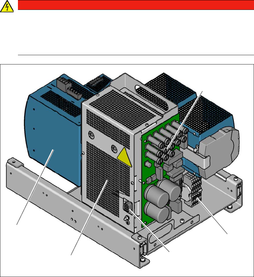
Fig. 2.8 - 2 Overview of the power supply unit
(1) Fuses
(2) Mains input terminals
(3) Connector to safety unit
(4) Safety contactors (behind the cover)
(5) Capacitor Module
DANGER
Dangerous voltages at the safety contactors after switching off the machine
After switching off the machine at the main switch, Pos. 4 - fig.
2.8 - 2 various compo-
nents (e.g. capacitors) at the power supply unit can carry dangerous voltages for approx.
5 minutes. The contactor unit is safely protected behind a cover.
Never open the cover of the safety contractors Pos. 4 - fig. 2.8 - 2.
(2)
(1)
(3)
(4)
(5)
2 Operational safety User manual E by SIPLACE
2.8 Residual voltages and discharge times in the machine From software version SC 712.1 Edition 05/2019
92
2.8.1.2 Machine switched off at the main power switch and disconnected
The machine is unpowered, apart from slight residual voltages in the power supply unit.
2.8.2 Residual voltages and discharge times after pressing the EMERGENCY STOP
button
If the EMERGENCY STOP button is pressed or the machine is switched off, the 300 VDC link volt-
age for the gantry axes and the 160 VDC link voltage for the star axes are reduced to harmless
residual voltages in a very short time.
2

User manual E by SIPLACE 2 Operational safety
From software version SC 712.1 Edition 05/2019 2.9 Disabling the compressed air supply and discharging the pressure
93
2.9 Disabling the compressed air supply and discharging the
pressure
The compressed air working pressure of the machine is set to 0.50 ± 0.025 MPa (5.0 ± 0.25 bar).
The position of the compressed air unit is shown at item 1 in fig. 2.9 - 1, page 94 ) The supply of
compressed air to the machine can be interrupted with the shutoff valve (item 2 in fig. 2.9 - 1, page
94 ).
Release and open the cover.
Lift the cover (see fig. 2.9 - 1, page 94).
Turn the lever of the shutoff valve (item 5 of fig. 2.9 - 1, page 94) from the vertical to the hor-
izontal position.
Monitor the operating pressure manometer (item 2+3 in fig. 2.9 - 1, page 94 ). When the ma-
chine is switched on, the pressure discharges to 0 MPa (0 bar) within 1 minute.
2
CAUTION
Interruption to compressed air supply!
When the machine is switched on, do not use the stop valve to interrupt the com-
pressed air supply for more than 30 minutes.
If you need to shut off the pneumatic system for longer in order to carry out cleaning
and checking or servicing work, you must switch the machine off at the main switch
and disconnect it from the machine voltage supply.