User Manual E-by-SIPLACE 用户手册.pdf - 第117页
User manual E by SIPLACE 3 Technical data and assemblies From software version SC 712.1 Edition 05/2019 3.5 Placement hea d 117 3.5 Placement head 3.5.1 SIPLACE CP14 for ve ry high speed placement Item no. 03109887-xx, S…
3 Technical data and assemblies User manual E by SIPLACE
3.4 Overviews of the modules From software version SC 712.1 Edition 05/2019
116
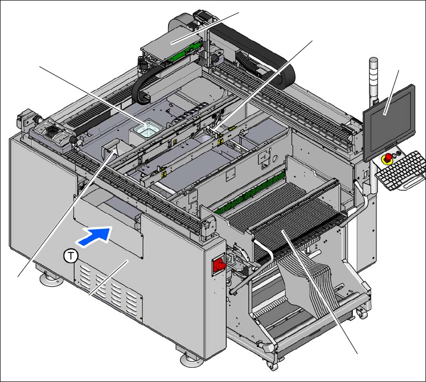
3.4.2 Overview of E by SIPLACE single sided assemblies
3
3
Fig. 3.4 - 2 E by SIPLACE single sided machine - overview of assemblies
(1) Basic module
(2) Reject bin
(3) Stationary cameras (optional)
(4) Gantry with placement head (according to the configuration)
(5) PCB conveyor (single conveyor)
(6) Monitor with keyboard at location 1
(7) Changeover table at location 1
(T) Direction of PCB transport
(1)
(4)
(5)
(6)
(7)
(2)
(3)
User manual E by SIPLACE 3 Technical data and assemblies
From software version SC 712.1 Edition 05/2019 3.5 Placement head
117
3.5 Placement head
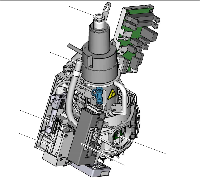
3.5.1 SIPLACE CP14 for very high speed placement
Item no. 03109887-xx, SIPLACE CP14 (without camera)
Item no. 03105195-xx, Component camera, type 23 GigE
3
Fig. 3.5 - 1 SIPLACE CP14 - function group part 1
(1) DP drive, 14 drives
(2) Pressure control valve
(3) Z motor (linear motor)
(4) Return cylinder
(5) Line for the exhaust air from the pressure control valve (2)
(6) Compressed air connection for 14 Venturi nozzles in the pickup/placement and holding circuit
(1)
(2)
(3)
(4)
(5)
(6)
3 Technical data and assemblies User manual E by SIPLACE
3.5 Placement head From software version SC 712.1 Edition 05/2019
118
3
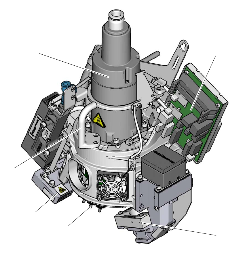
Fig. 3.5 - 2 SIPLACE CP14 - function group part 2
(1) Component camera, type 23 GigE
(2) Star with 14 nozzles
(3) Component sensor
(4) Handle
(5) Star motor
(6) Intermediate distributor board
(1)
(2)
(3)
(4)
(5)
(6)