User Manual E-by-SIPLACE 用户手册.pdf - 第183页
User manual E by SIPLACE 4 Setting up and commissioning From software version SC 712.1 Edition 05/2019 4.2 Infrastructur e at the installation location 183 Overview of the fuses 4 4 Fig. 4.2 - 6 Overview of the fuses – F…
4 Setting up and commissioning User manual E by SIPLACE
4.2 Infrastructure at the installation location From software version SC 712.1 Edition 05/2019
182
4.2.3.5 Connecting the power supply cable
Crimp a ferrule onto each end of the wire.
Loosen the nuts on the cable fixture.
Run the mains power cable through the cable fixture to the terminal panel X100:1.
Connect L1/L2/L3 to Q1:1 / Q1:3 / Q1:5 respectively. PE connect to terminal block X100:1
Make sure that the bending radius is adequate. The wires must not be kinked.
Manually tighten the cable fixture.
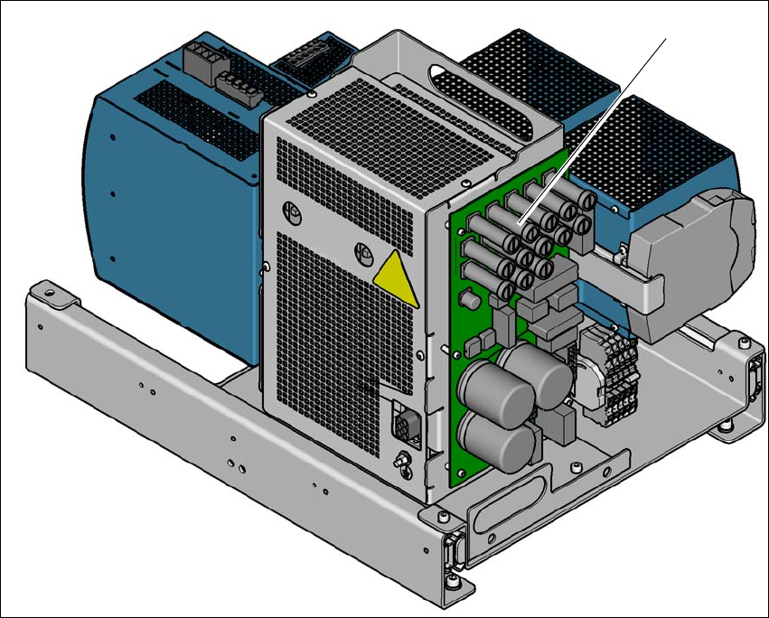
4.2.3.6 Checking the micro-fuses
Low voltages (24 V and 42 V) and the intermediate circuit voltage of the head motors are fused
by micro-fuses.
4
Fig. 4.2 - 5 Micro-fuses on the distribution board of the power supply
(1) Micro-fuses on the distribution board of the power supply
(1)
User manual E by SIPLACE 4 Setting up and commissioning
From software version SC 712.1 Edition 05/2019 4.2 Infrastructure at the installation location
183
Overview of the fuses 4
4
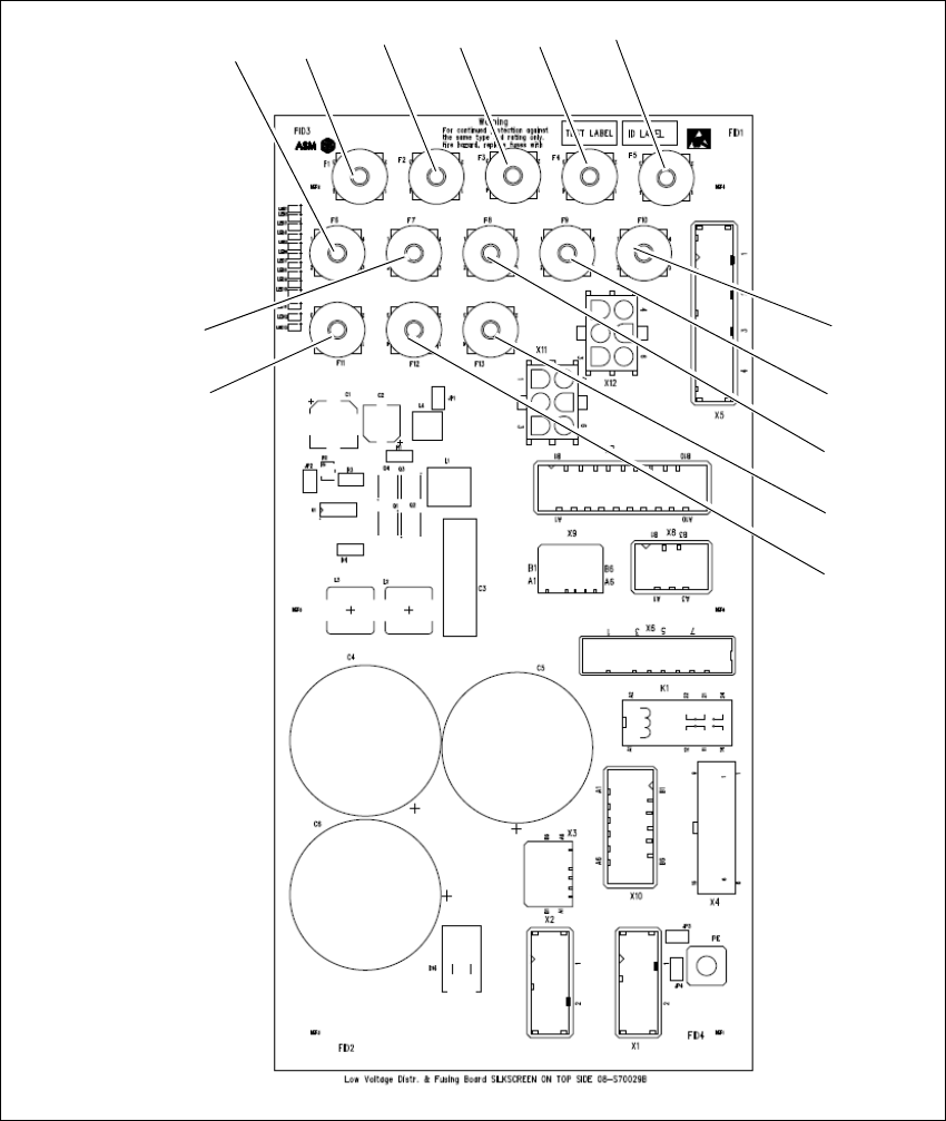
Fig. 4.2 - 6 Overview of the fuses
– F1: not used
– F2: PC1 supply (24 V)
– F3: Conveyor supply (24V)
– F4: Safety Relays supply (24 V)
F1 F2 F3 F4 F5
F6
F7
F8
F9
F10
F11
F12
F13
4 Setting up and commissioning User manual E by SIPLACE
4.2 Infrastructure at the installation location From software version SC 712.1 Edition 05/2019
184
– F5: Safety contactors supply (24V)
– F6: Power fail signal (24 V)
– F7: MGCU supply (24V)
– F8: Distributor supply (24 V)
– F9: FCU1 supply (24V)
– F10: FCU 2 supply (24V)
– F11: Vision flash voltage (42 V)
– F12: Head drives supply(42V)
– F13: Conveyor supply (42V)