Printer 600 Machine Programming.pdf - 第3页
0$&+,1 (352*5$0 0,1* ,1752'8& 7,21 Software Version 07SP04 User Manual 1.3 Figure 1-2 Front V iew of Machine with Printhead Shut ter Item Description 1 T ricol oured B eacon 2 System Button - F ront 3 Emerg…
0$&+,1(352*5$00,1*
,1752'8&7,21
1.2 User Manual Software Version 07SP04
Machine Overview Displayed in graphics below are the different types of machine cover packages
and controls:
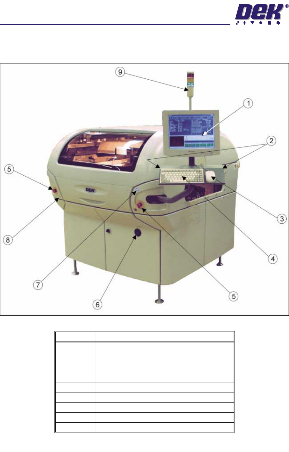
Figure 1-1 Front View of Machine with Printhead Covers
Item Description
1 Touchscreen Monitor
2 Two Button Control
3 Mouse
4 Keyboard
5 Emergency Stop Buttons (E Stop)
6 Mains Isolator Switch
7 System Button
8 Paste Roll Lamp Button
9 Tricoloured Beacon
0$&+,1(352*5$00,1*
,1752'8&7,21
Software Version 07SP04 User Manual 1.3
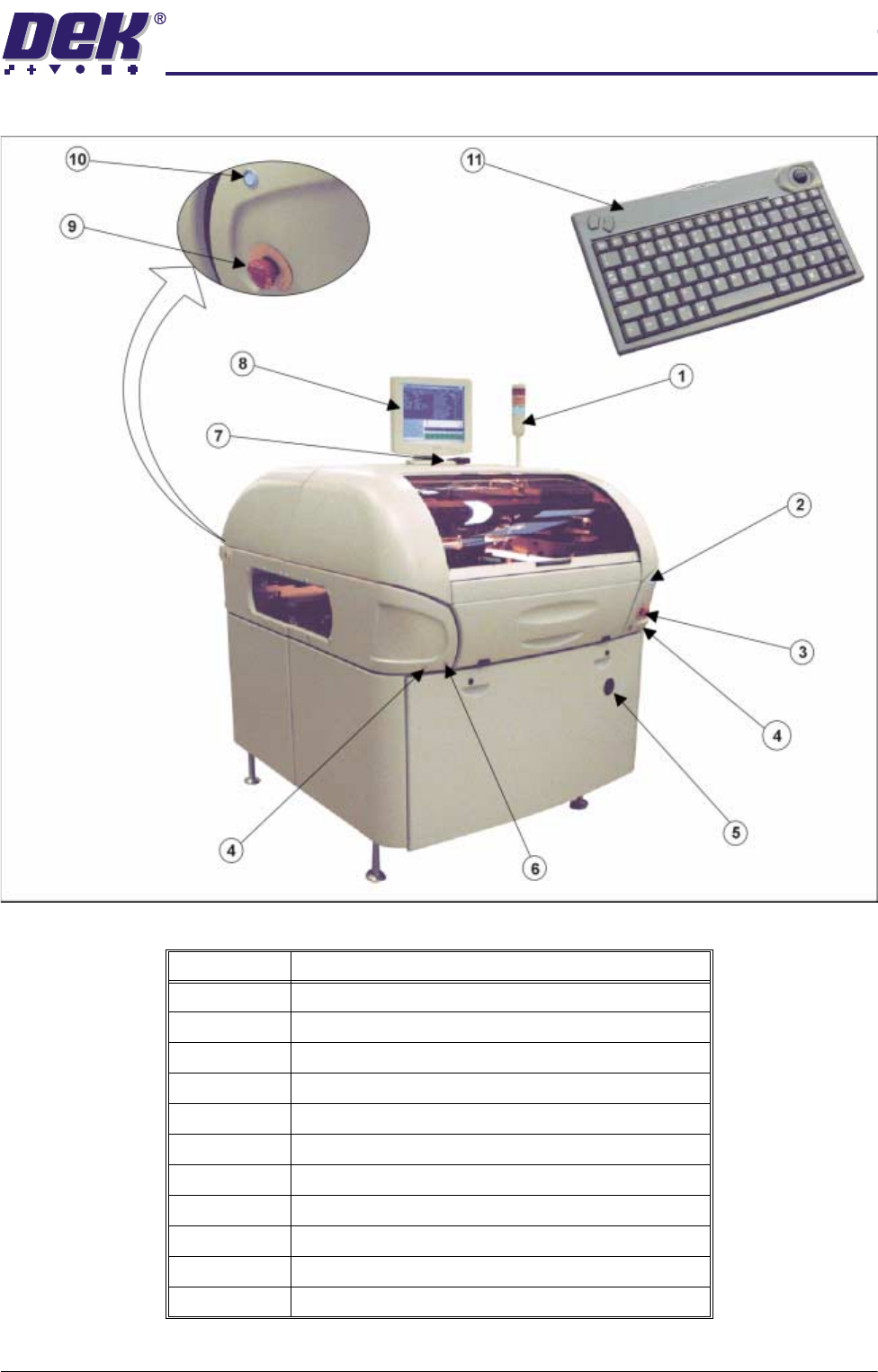
Figure 1-2 Front View of Machine with Printhead Shutter
Item Description
1 Tricoloured Beacon
2 System Button - Front
3 Emergency Stop Button (E Stop) - Front
4 Two Button Control
5 Mains Isolator Switch
6 Paste Roll Lamp Button
7 IR Receiver
8 LCD Monitor
9 Emergency Stop Button (E Stop) - Rear
10 System Button - Rear
11 IR Keyboard/Mouse
0$&+,1(352*5$00,1*
67$*(32:(583$1'/2*21
1.4 User Manual Software Version 07SP04
STAGE 1 - POWER UP AND LOG ON
For machines with the remote board stop option, ensure that the machine is
correctly configured for the intended product. Carry out the appropriate one of
the following procedures:
• Camera to Remote Board Stop - LHS Configuration
• Camera to Remote Board Stop - RHS Configuration
• Remote Board Stop - LHS to RHS Configuration
• Remote Board Stop - RHS to LHS Configuration
• Remote Board Stop - Same Side Configuration
• Remote Board Stop to Camera Board Stop
See Technical Reference Manual, Rising Table Module Chapter, Replacement
Procedures, for the first five procedures and Technical Reference Manual,
Camera and Vision System Module Chapter, Replacement Procedures for the
Remote Board Stop to Camera Board Stop procedure.
CAUTION
CAMERA BOARD STOP.
To prevent damage to the camera board stop the
remote board stop must be used for product boards over 1kg in weight.
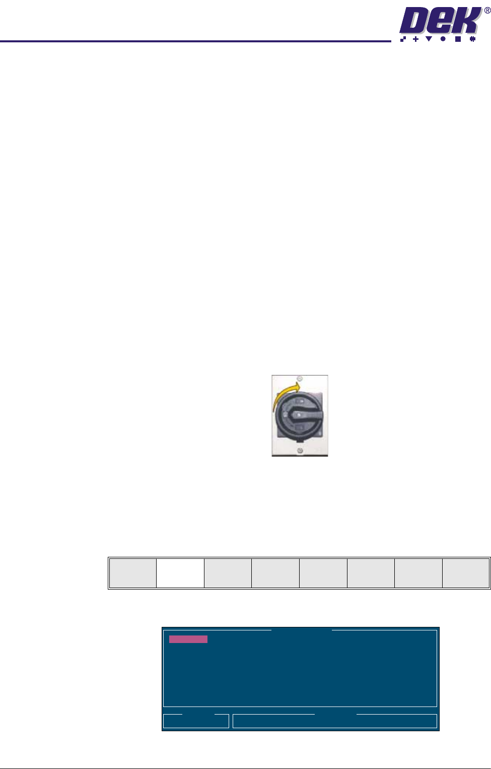
1. Turn the mains isolator switch to ON.
2. When the message ‘Press SYSTEM Switch To Initialize Printer or Select
Diagnostics or Load Data’ is displayed in the message prompt bar, either:
a. Select Load Data (F2) if the loaded product is unknown or needs to be
changed.
b. Go to Step 6 if the loaded product file is known to be the correct one.
The following Load Data File window is displayed:
Load
Data
Diagnost
Load Data File
Product ID
Search
Training
265TEST1
265TEST1
ANDY H
CALIBRA
DEFAULT
DEK04
DEK06