Printer 600 Machine Programming.pdf - 第63页
0$&+,1 (352*5$0 0,1* 67$*( ()250 )/(;722/,1* Software Version 07SP04 User Manual 1.63 14. Select Ex it (F8). 15. Prepar e the universal set plate for the current pr oduct stenc il a s follows : a. For a 20 ″ I…
0$&+,1(352*5$00,1*
67$*(()250)/(;722/,1*
1.62 User Manual Software Version 07SP04
cleaner are moved to the rear.
The Change Tooling Parameters window is displayed:
NOTE
If the remote board stop is fitted the Board Stop X and Board Stop Y
parameters are replaced by Remote Board Stop X.
9. Setting up the board stop position is automatically done using the board
dimensions previously set in the product file. If they need adjustment to re-
position the board stop for any reason, ie any routing on the board edge or
a badly positioned image on the stencil, this can be done now. If adjustment
is necessary continue with Step 9. If adjustment is not necessary go to Step
14.
10.Select Adjust (F1).
NOTE
If Auto Rail Width in Set Prefs is set to disabled, Full Width and Load Width
are not available.
11.Use the Next and Previous keys (F4 - F5) to highlight each parameter.
12.Use the Incr. and Decr. keys (F6 - F7), or the forward slash key (/) on the
keyboard, to change the parameter value.
13.Select Save (F2). The message ‘Saving fiducial data - Please wait Board
data file saved’ is displayed.
Mode
Load
Data
Edit
Data
Setup
Squeegee
Change
Screen
Change
Tooling
Change
Language
Exit
Change Tooling Parameters
BOARD WIDTH
BOARD STOP X
BOARD STOP Y
UNDER CLEARANCE
216.0
125.0
142.6
19.0
mm
mm
mm
mm
Adjust
Open
Cover
Home
Cleaner
Board
Stop
Full
Width
Load
Width
Generic
Tool ing
Exit
Save Next Previous Incr. Decr. Exit
Save Next Previous Incr. Decr. Exit
Save Next Previous Incr. Decr. Exit
0$&+,1(352*5$00,1*
67$*(()250)/(;722/,1*
Software Version 07SP04 User Manual 1.63
14.Select Exit (F8).
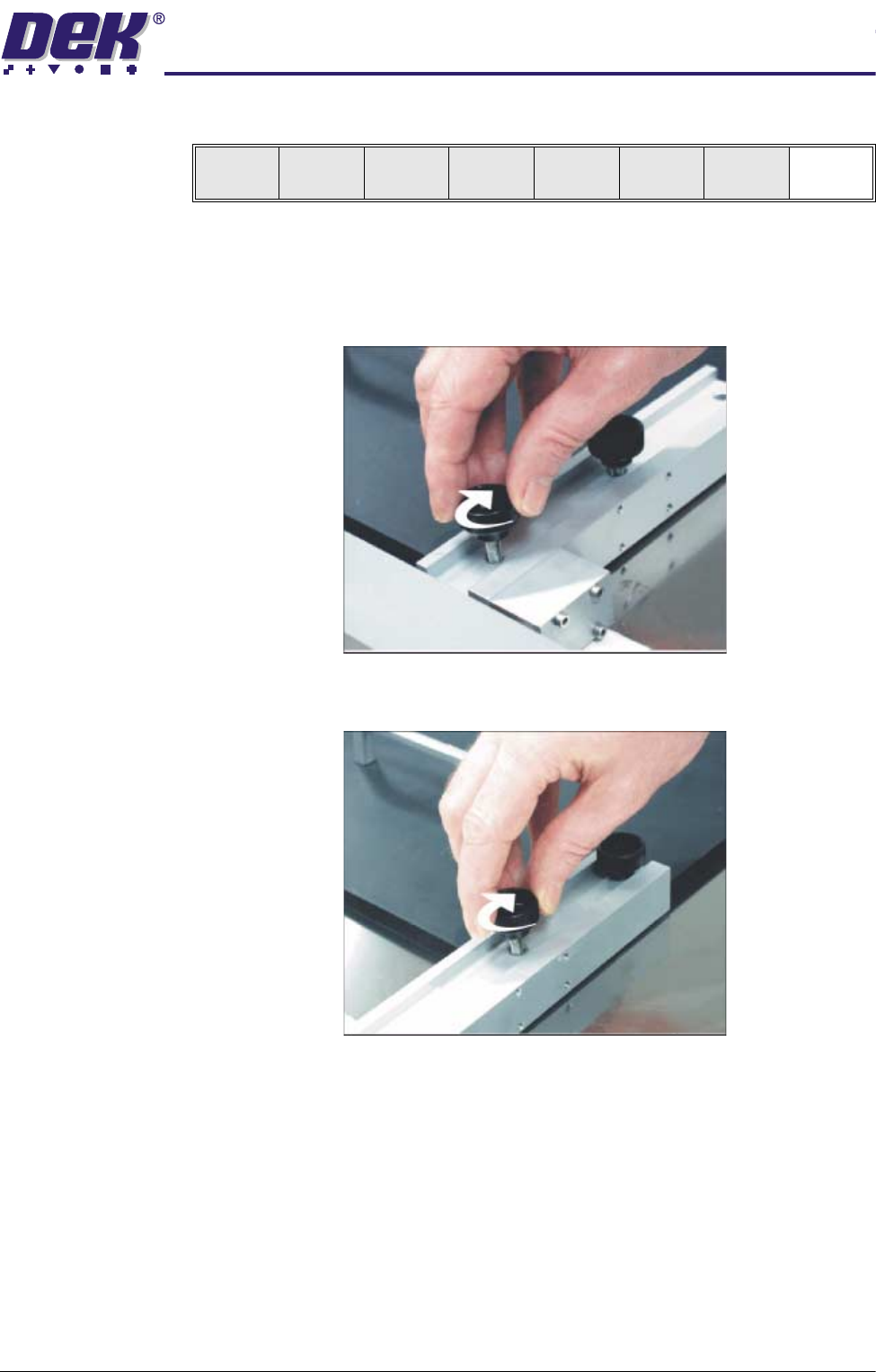
15.Prepare the universal set plate for the current product stencil as follows:
a. For a 20″ I/D stencil, secure the two left hand rod mounts to the plate by
means of the two knurled thumbscrews through the outer and centre
mounting holes in the mount assembly.
b. For a 23″ I/D stencil or larger, secure the rod mounts to the plate using
the centre and inner mounting holes.
16.Position the set plate in the stencil centrally over the image, ensuring the
rods of the rod mounts are in contact with the left hand stencil side.
17.Adjust the position of the right hand spring lock assemblies by releasing the
two knurled thumbscrews and sliding the assembly towards the side of the
Save Next Previous Incr. Decr. Exit
0$&+,1(352*5$00,1*
67$*(()250)/(;722/,1*
1.64 User Manual Software Version 07SP04
stencil.
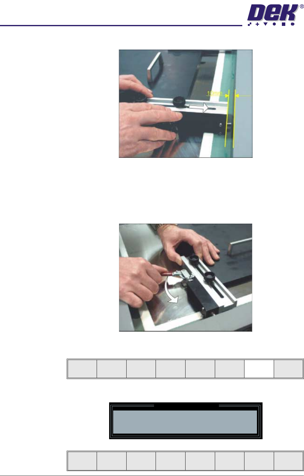
18.Ensure there is a 10mm gap between the stencil side and the end of the
spring lock assembly.
19.Tighten the thumbscrews of the two spring lock assemblies.
20.Ensuring the set plate remains parallel to the stencil sides operate the toggle
clamps to extend the piston shafts against the right hand stencil side. Thus,
clamping the set plate to the inside of the product stencil.
21.Select Generic Tooling (F7). The print carriage moves to the front of the
machine.
The following window and menu bar are displayed:
Adjust
Open
Cover
Home
Cleaner
Board
Stop
Full
Width
Load
Width
Generic
Tooling
Exit
Generic Tooling Warning
WARNING Paste may drip into the machine
Remove Squeegees NOW
Continue
Open
Cover
No