Printer 600 Machine Programming.pdf - 第42页
0$&+,1( 352*5$00 ,1* 67$*(& '(',& $7('722/ ,1* 1.42 User Manual Software Ve rsion 07SP04 50. Press the System but ton. 51. Select Change Screen (F2) . 52. Go to S tage 6. Mode Load Data …
0$&+,1(352*5$00,1*
67$*(&'(',&$7('722/,1*
Software Version 07SP04 User Manual 1.41
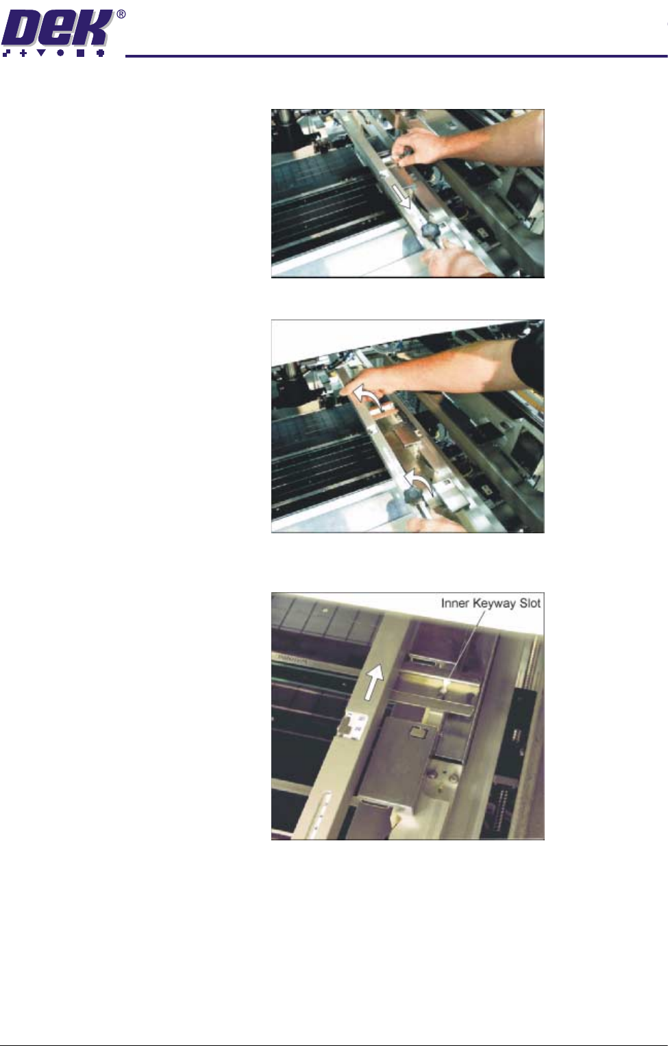
a. Slide the screen depth adjuster towards the front of the machine.
b. Lift the adjuster clear of the two locating screws.
c. Using the inner pair of keyway slots locate the adjuster on the chase and
slide the adjuster to the rear of the machine to lock in place.
47.Ensuring for the correct orientation of the stencil, load the stencil against the
left hand chase rail.
48.If fitted, toggle screen clamp switch to down position (on).
49.Either:
a. Close the front printhead cover.
or
b. Raise the drop down panel and lower the printhead shutter.

0$&+,1(352*5$00,1*
67$*(&'(',&$7('722/,1*
1.42 User Manual Software Version 07SP04
50.Press the System button.
51.Select Change Screen (F2).
52.Go to Stage 6.
Mode
Load
Data
Edit
Data
Setup
Squeegee
Change
Screen
Change
Tool ing
Change
Language
Exit
0$&+,1(352*5$00,1*
67$*('08/7,)/(;722/,1*
Software Version 07SP04 User Manual 1.43
STAGE 5D - MULTIFLEX TOOLING
WARNING
BOARD CLAMPS. EXTREME CARE MUST BE EXERCISED WHEN WORKING IN
THE TOOLING AREA OF THE MACHINE TO AVOID INJURY. THE FOILS ON THE
FRONT AND REAR BOARD CLAMPS ARE VERY SHARP.
CAUTION
BOARD CLAMPS.
Care must be taken to ensure that the board clamps are
not damaged when removing or replacing tooling.
NOTE
Setting up the MultiFlex tooling is to be performed off the machine.
1. Create a box the same size as the board using the side plates.
2. Use the board width and board length dimensions to position the box
correctly.
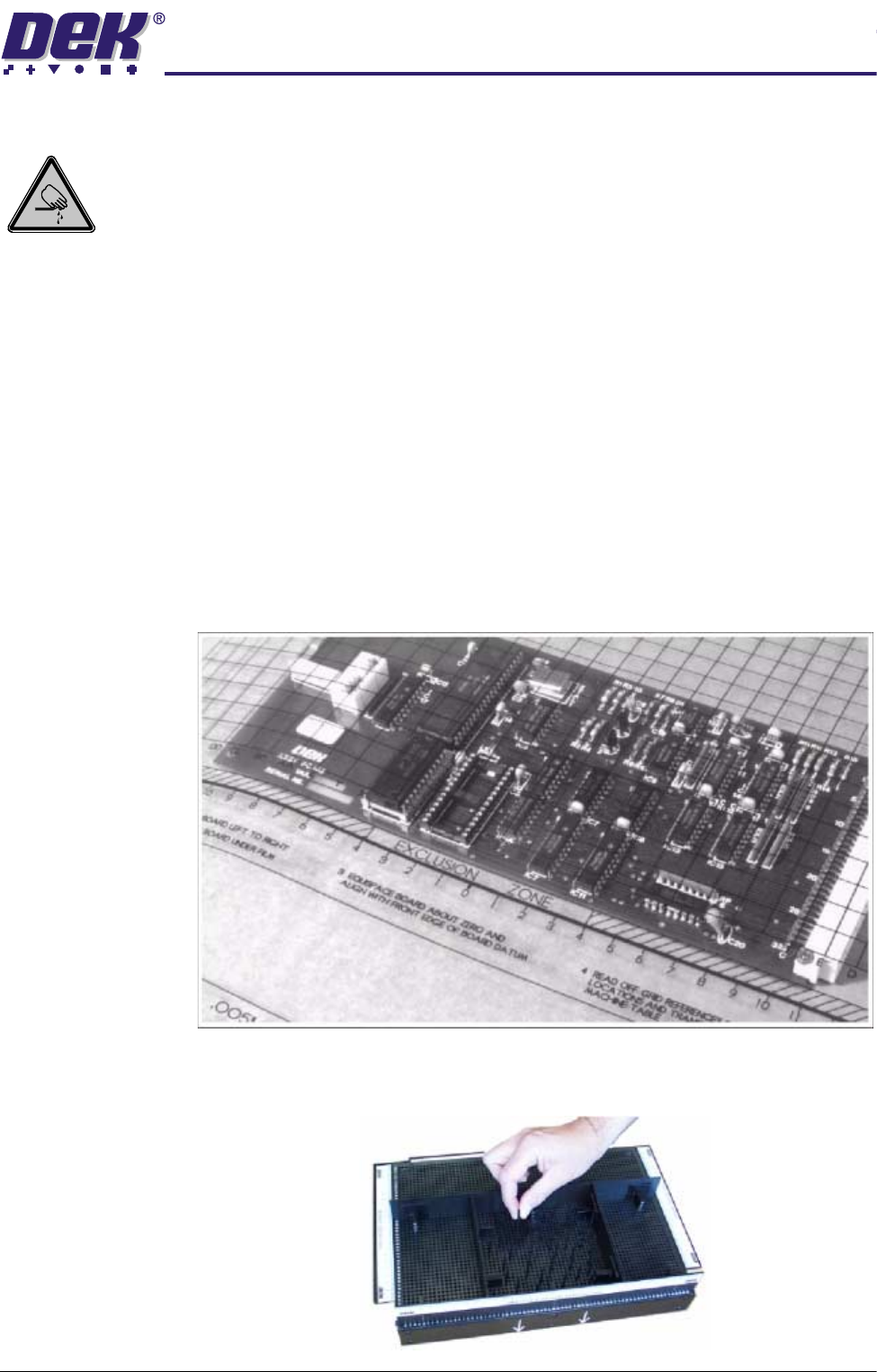
3. Place the PCB on a flat surface, component side up.
4. Position the acetate template, supplied with the tooling, over the PCB such
that the front edge of the board is aligned with the arrow indicators on the
template. Ensure that the centreline of the board is aligned with the template
zero.
5. Using the grid coordinates marked on the template, position pins which
coincide with gaps between the underside board components.