Printer 600 Machine Programming.pdf - 第84页
0$&+,1( 352*5$00 ,1* 67$*( 35,17,1 67(302'( 1.84 User Manual Software Ve rsion 07SP04 4. Load the solder p aste onto the stenc il. 5. Either: a. Close the front printhead cover . or b. Raise the drop do…
0$&+,1(352*5$00,1*
67$*(35,17,167(302'(
Software Version 07SP04 User Manual 1.83
STAGE 7 - PRINT IN STEP MODE
If using squeegees with paste dispenser continue with Section Auto Paste
Dispense. If using squeegees without paste dispenser go to Section Manual
Paste Load. If using ProFlow go to Section Run a Product in Step Mode.
Auto Paste
Dispense
1. Select Paste Load (F3).
2. Select Auto Dispense (F1).
3. Select Exit (F8).
4. Go to Section Run a Product in Step Mode.
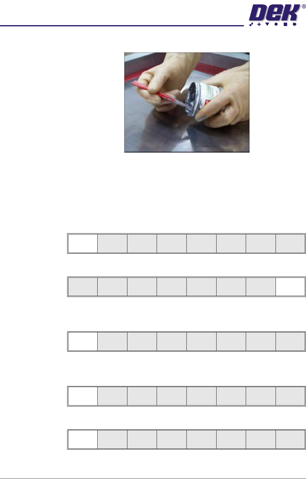
Manual Paste Load
WARNING
SOLDER PASTE AND SOLVENTS. WHEN USING OR HANDLING ANY SOLDER
PASTE OR SOLVENT FORMULATION THE MANUFACTURERS’ RECOMMEND
SAFETY PRECAUTIONS MUST BE STRICTLY ADHERED TO.
1. Select Paste Load (F3).
2. Select Manual Load (F2).
3. Either:
a. Open the front printhead cover.
or
b. Raise the printhead shutter and lower the drop down panel.
Run
Open
Cover
Paste
Load
Clean
Screen
Adjust Setup Monitor Maint.
Auto
Dispense
Manual
Load
Load
Cart.
Print
Directn
Exit
Auto
Dispense
Manual
Load
Load
Cart.
Print
Directn
Exit
Run
Open
Cover
Paste
Load
Clean
Screen
Adjust Setup Monitor Maint.
Auto
Dispense
Manual
Load
Load
Cart.
Print
Directn
Exit
0$&+,1(352*5$00,1*
67$*(35,17,167(302'(
1.84 User Manual Software Version 07SP04
4. Load the solder paste onto the stencil.
5. Either:
a. Close the front printhead cover.
or
b. Raise the drop down panel and lower the printhead shutter.
6. Press the System button.
7. Select Continue (F1).
8. Select Exit (F8)
Run a Product in
Step Mode
1. Select Run (F1).
2. Load a board on to the conveyor.
3. Select Auto Board (F1).
4. Select Step (F1).
Continue
Auto
Dispense
Manual
Load
Load
Cart.
Print
Directn
Exit
Run
Open
Cover
Paste
Load
Clean
Screen
Adjust Setup Monitor Maint.
Auto
Board
Manual
Board
Knead
Paste
Exit
Step
Open
Cover
Inspect
Setup
Single Exit
0$&+,1(352*5$00,1*
67$*(35,17,167(302'(
Software Version 07SP04 User Manual 1.85
5. Select Step (F1).
6. Select Step (F1).
7. Select Step (F1).
8. Select Step (F1)
9. Select Step (F1)
10.Select Step (F1)
11. Select Auto Board (F1)
12.Remove the board from the conveyor and inspect the print for alignment. If
the alignment is satisfactory go to Step 16, if the alignment needs adjusting,
calculate the following:
X Offset, Y Offset and θ Offset.
13.Select Edit Data (F3)
14.Enter the X Offset, Y Offset and θ Offset, calculated in Step 12 to both the
Forward and Reverse set of offsets.
15.Repeat Steps 1-12 until the alignment is correct for both a forward and
reverse print.
16.If 2D Inspection is being used continue with Stage 8, if 2D Inspection isn’t
Step
Open
Cover
Inspect
Setup
Single Exit
Step
Open
Cover
Fiducial
Setup
Adjust
Search
Step
Search
Reset
Single Exit
Step
Open
Cover
Fiducial
Setup
Adjust
Search
Step
Search
Reset
Single Exit
Step
Open
Cover
Fiducial
Setup
Adjust
Search
Step
Search
Reset
Single Exit
Step
Open
Cover
Fiducial
Setup
Adjust
Search
Step
Search
Reset
Single Exit
Step
Inspect
setup
Single Exit
Auto
Board
Manual
Board
Single Exit
Auto
Adjust
Load
Data
Edit
Data
Setup
Squeegee
Change
Screen
Change
Tool ing
Change
Language
Exit