OM-1076-001.pdf - 第102页
B01 Shape Data (B01_10) 01 11-002 2-76 Tg0502-PM-CL (b) When the "Lead T ype" is Electric Contact or the "Lead T ype Shape" of the connectors or other leaded components is Round or Eccentric, set Fron…
B01 Shape Data (B01_10)
0107-001 2-75 Tg0502-PM-CL
Fig. B155
Top Posn (Long) Det [mm]
+99.999
Center Posn (Latl) Det [mm]
+99.999
Lead
No.
1
Fig. B156
Fig. B157
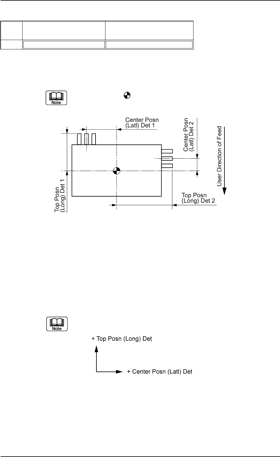
(10) Lead Group Center Posn (Latl) Det and Top Posn (Long) Det
Set the location of the lead groups in the text boxes.
Set the distance from the reference position where the outward length
is specified.
The center of the
mark is the reference position for outward length
setting.
Top View of Component
Unit: mm
Data Input Range
Center Position : −99.999 to +99.999
Prior Position : −99.999 to +99.999
Applicable Components : IC (Complex), Connector (Complex),
and Other Leaded (Complex)
(a) The coordinate system is as follows.
Note: The above-described coordinate system also rotates accord-
ing to the direction of a group.
B01 Shape Data (B01_10)
0111-002 2-76 Tg0502-PM-CL
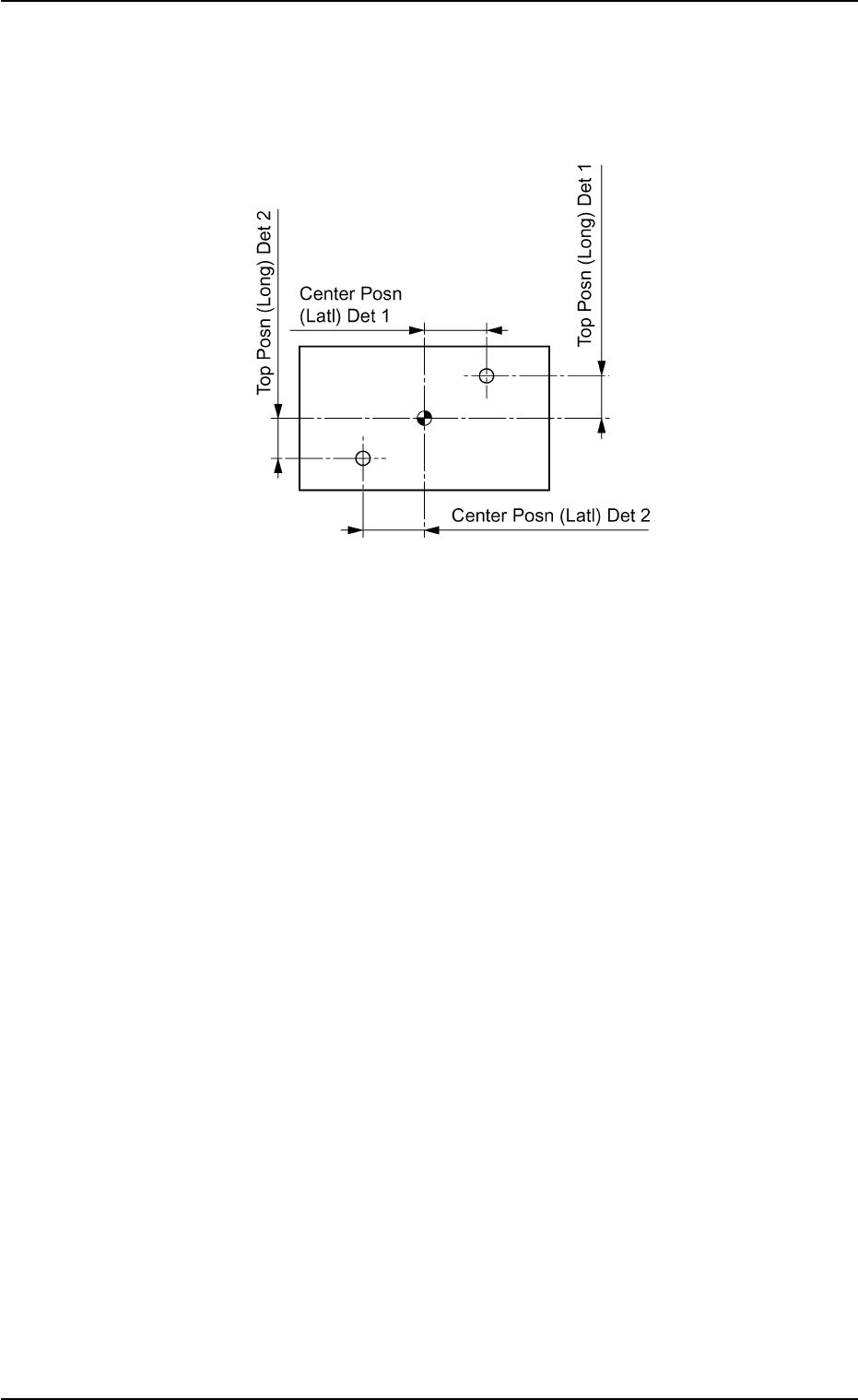
(b) When the "Lead Type" is Electric Contact or the "Lead Type Shape"
of the connectors or other leaded components is Round or Eccentric,
set Front End Position (Length) as the distance from the outer dimen-
sions setting reference position to the center of the lead group.
Fig. B158
Top View of Component
(B01_11) Electrical Contact Data
The following is the basic setting for component electrical contact.
Applicable Components: BGA/CSP
B01 Shape Data (B01_11)
0107-001 2-77 Tg0502-PM-CL
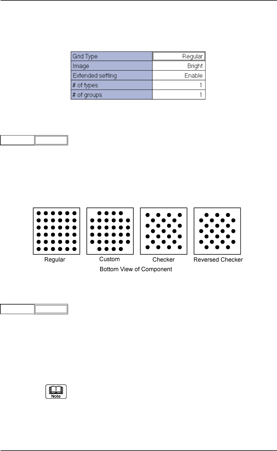
(1) Grid Type
Select one of the following options to designate the grid type.
Regular : Normal Grid Arrangement
Custom : Grid Arrangement without Balls at Four Cor-
ners
Checker : Staggered Arrangement
Reversed Checker : Reversed Staggered Arrangement
Fig.B160
Grid Type Regular
(2) Image
Select one of the following options to designate the brightness in com-
parison with the mold when an image of electrical contact is captured
in the normal lighting system.
Bright : Select this when the captured image looks brighter than
the mold.
Dark : Select this when the captured image looks darker than
the mold.
(a) In normal cases, select "Bright".
(b) When the mold of a BGA component is made of ceramic, selecting
"Dark" could have good results.
Fig.B162
Image Bright
Fig. B159 Edit Window (Example) for BGA/CSP Components
Fig. B161