OM-1076-001.pdf - 第38页
(17) Cmpnt Detection (Sensor) Set whether to judge the pick-up quality with the vacuum sensor . "DISABLE" or "ENABLE" can be selected. When the nozzle selected in "Selected NOZZLE" meets one…
(13) Nozzle Change
Select one of the following options to designate the rate of the nozzle
change speed reduction when a component is picked up.
Full Speed 10% Decr 20% Decr 30% Decr 40% Decr
50% Decr 60% Decr 70% Decr 80% Decr 90% Decr
(14) Recognition Time [sec] (Disable)
Set the approximate time required for component recognition process-
ing in the data box.
Unit: second
Data Input Range: 0.00 to 9.99
This set parameter is used to process the optimization.
(15) Pu Retention Time [sec]
Set the retention time for the nozzle at the lower limit when a compo-
nent is picked up.
Unit: second
Data Input Range: 0.00 to 1.99
This function can be used when the pick-up is not stable due to the influ-
ence of the component pick-up surface or some incompatibility with the
nozzle.
(16) Pl Retention Time [sec]
Set the retention time for the nozzle at the lower limit when a compo-
nent is placed.
Unit: second
Data Input Range: 0.00 to 1.99
A02 Control Data (A02_01)
0111-002 2-19 Tg0502-PM-CL
Fig.B26
Nozzle change
Full Speed
Fig.B27
Recognition time [sec]
0.00
Fig.B28
Pu retention time [sec]
0.00
Fig.B29
Pl retention time [sec]
0.00
(17) Cmpnt Detection (Sensor)
Set whether to judge the pick-up quality with the vacuum sensor.
"DISABLE" or "ENABLE" can be selected.
When the nozzle selected in "Selected NOZZLE" meets one of the re-
quirements described in the table below, "DISABLE" is selected auto-
matically.
Table B11
(18) Air blow
From the following items, select whether or not to air blow when the
component is placed.
Enable Disable
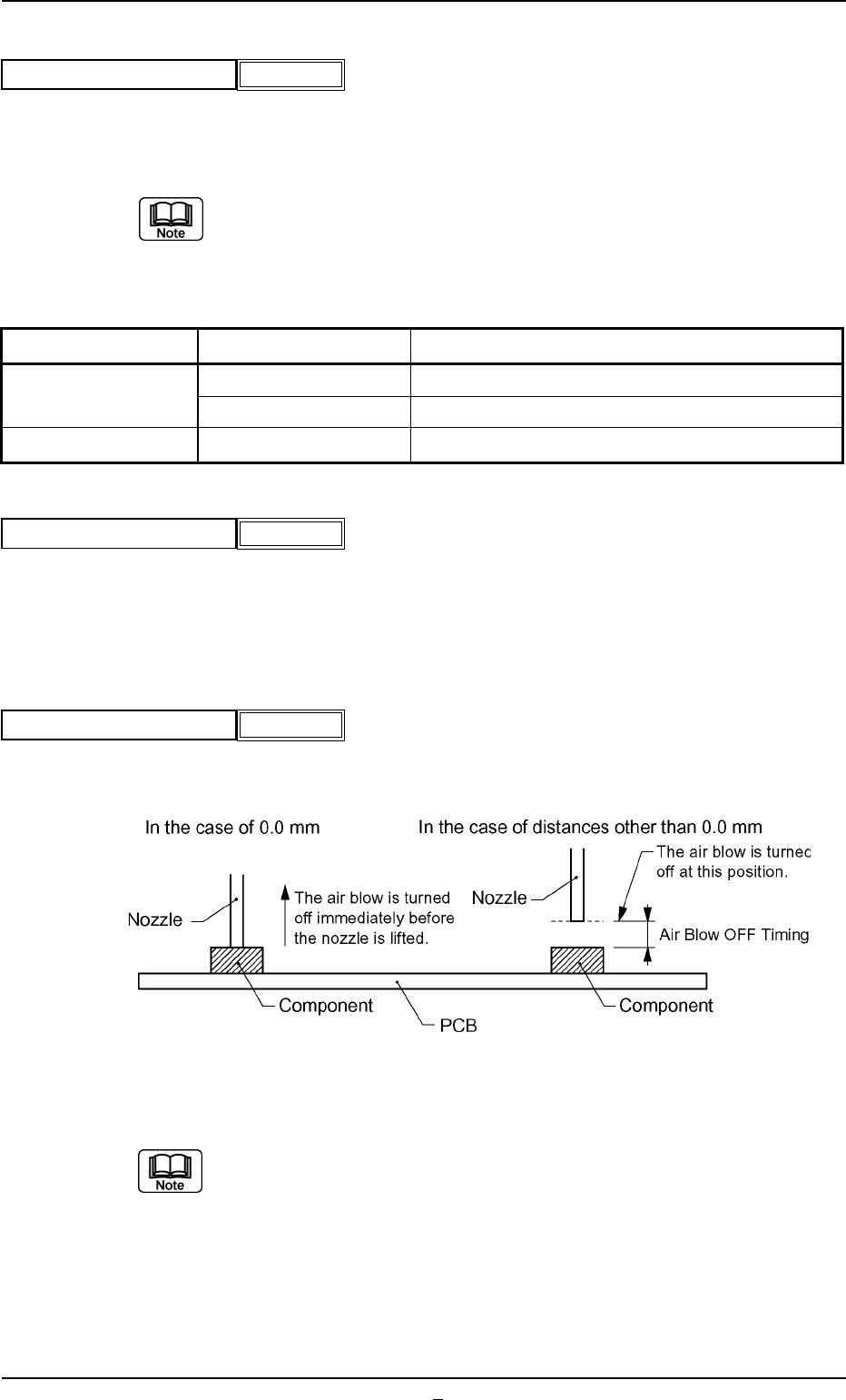
(19) Air blow off timing [mm]
Set the position at which the air blow is turned off.
This function is used when the nozzle error occurs where component
is brought back.
Unit: mm
Data Input Range: 0.0 to 9.9
A02 Control Data (A02_01)
0206-003 2-20 Tg0502-PM-CL
Fig.B30
Cmpnt detection (Sensor)
Disable
Fig.B30-1
Air blow
Enable
Fig.B30-2
Air blow off timing [mm]
0.0
Fig. B30-3
Item Condition Remarks
Nozzle ID EC** Mechanical Chuck Nozzle
EE** Mechanical Chuck Nozzle
Area of Pick-Up Hole Less then 0.7854mm
2
Total Area of Pick-Up Hole
A02 Control Data (A02_02)
0206-001 2-20-1 Tg0502-PM-CL
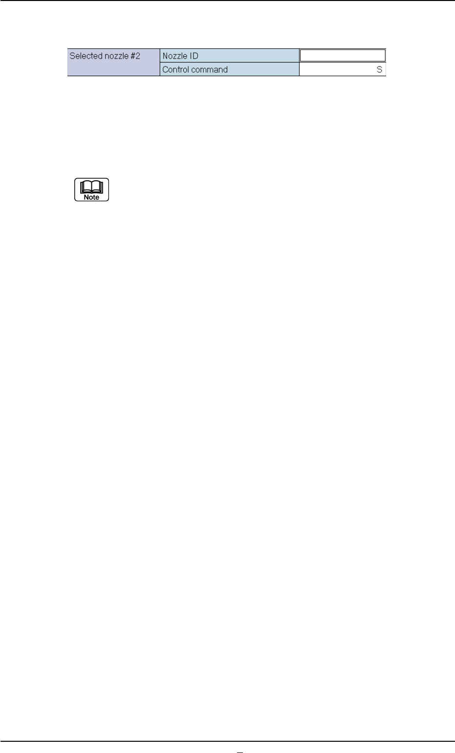
(A02_02) Selected Nozzle #2
Set the nozzle to be used when the nozzle selected in the "Selected
Nozzle #1" data box can not be used.
Refer to "Selected Nozzle #1" for the descriptions for each data.
Nozzles are distinguished according to the difference in end size, shape,
length, etc., and managed using nozzle ID.s.
Fig. B31