OM-1076-001.pdf - 第66页
B01 Shape Data (B01_02) 0107-001 2-42 Tg0502-PM-CL (b) Example: T ≠ t Side View (3) Elctd Size [mm] Set the width of the component's electrode. This data is used exclusively for front lighting recognition. Unit: mm …
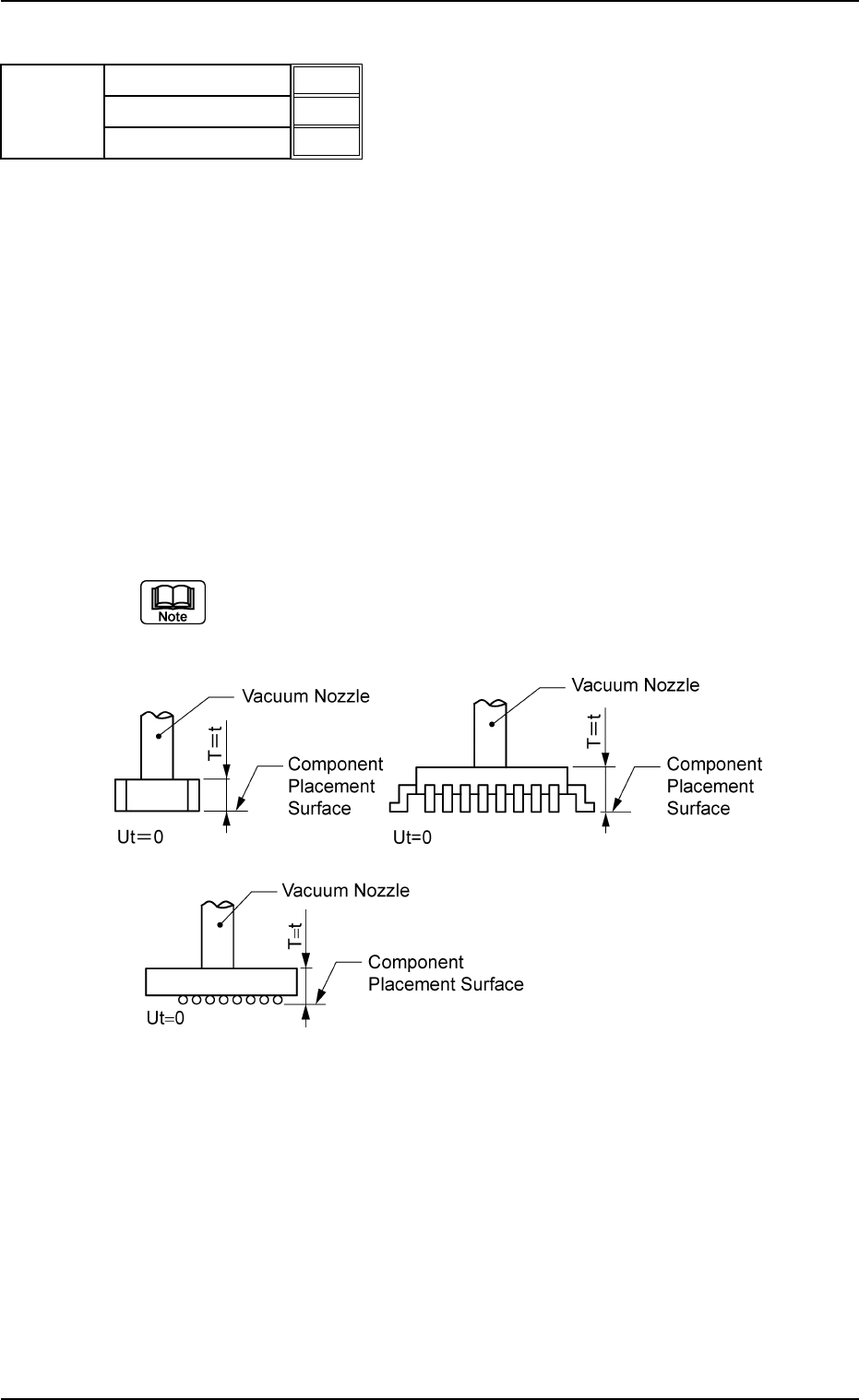
(2) T (Thickness) [mm], t (Thickness) [mm], Ut (Thickness) [mm]
Set the thickness of the component.
T (Thickness) : Thickness between Component Placement and
Uppermost Surfaces
t (Thickness) : Thickness between Component Placement and
Nozzle Pickup Surfaces
Ut (Thickness): Thickness between Component Lowermost and
Placement Surfaces
Unit: mm
Data Input Range
T (Thickness) : 0.01 to 50.00
t (Thickness) : 0.01 to 50.00
Ut (Thickness): 00.00 to 50.00
Applicable Components:
Applicable for all subjected components
(a) Example : T = t
Side View
B01 Shape Data (B01_02)
0206-003 2-41 Tg0502-PM-CL
T (Thickness) [mm]
t (Thickness) [mm]
Ut (Thickness) [mm]
5.70
5.70
0.00
Fig. B82
Mold size
Fig. B83
B01 Shape Data (B01_02)
0107-001 2-42 Tg0502-PM-CL
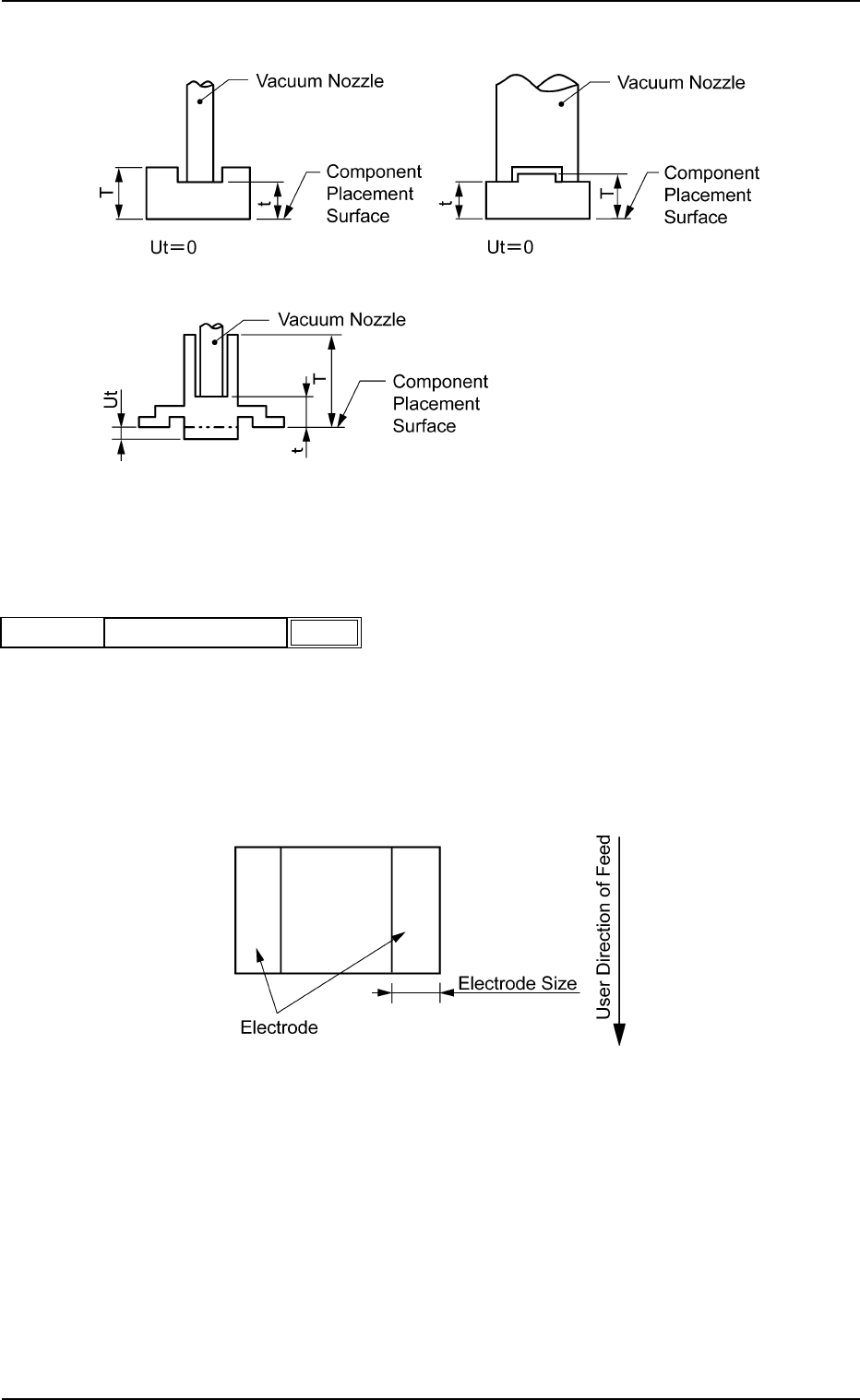
(b) Example: T ≠ t
Side View
(3) Elctd Size [mm]
Set the width of the component's electrode.
This data is used exclusively for front lighting recognition.
Unit: mm
Data Input Range: 0.00 to 99.99
Applicable Component: Square
Fig. B85
0.10
Elctd Size [mm]
Mold Size
Fig. B84
Fig. B86
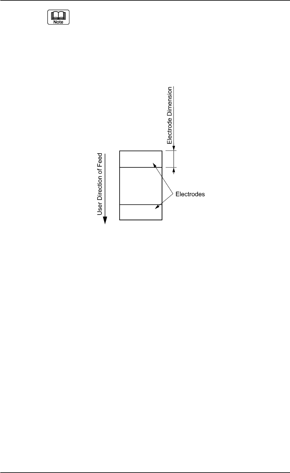
(a) Both right and left electrodes are identical in size.
(b) When the whole image of the component is reflected brightly, then
set this data to "0".
(c) When the electrodes are located in the user direction of component
feed as shown in the figure below, create each data as component
library data assuming that the electrodes are located as shown in the
figure above and set "90°" in the "Direction of the label "Carrier Data".
B01 Shape Data (B01_02)
0206-002 2-43 Tg0502-PM-CL
Fig. B88