OM-1076-001.pdf - 第77页
B01 Shape Data (B01_07) 01 11-002 2-53 Tg0502-PM-CL (B01_07) Linear Edge Data Set the linear edges which form the shape of a component. Applicable Components: Deform (Complex) (1) It is required to enter parameters (para…
(a) When "Straight" or "No Detection" is set in the "Shape" text boxes,
set "+00.00" in the "Detection Posn X" and "Detection Posn Y" text
boxes.
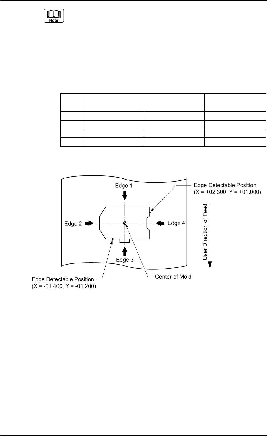
(b) When a component shape is similar to one in the figure below, set
each edge data as follows.
The condition of the corners is not used to detect the shape of the
edges.
Edges 1 and 2 in the above examples are detected as straight lines.
Table B14
No. Shape Detection Posn Detection Posn
X [mm] Y [mm]
1 Straight +00.000 +00.000
2 Straight +00.000 +00.000
3 Convexoconcave −01.400 −01.200
4 Convexoconcave +02.300 +01.000
Top View of Component
B01 Shape Data (B01_06)
0206-002 2-52 Tg0502-PM-CL
Fig. B108
B01 Shape Data (B01_07)
0111-002 2-53 Tg0502-PM-CL
(B01_07) Linear Edge Data
Set the linear edges which form the shape of a component.
Applicable Components: Deform (Complex)
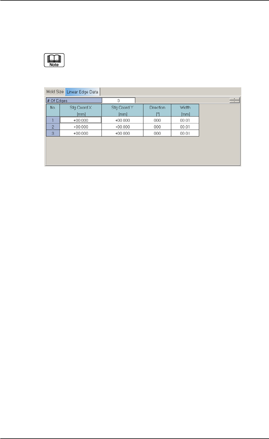
(1) It is required to enter parameters (parameters described in "(2)" to
"(4)") equivalent to the number of linear edges specified in the "# of
Edges" data box.
Definition of Linear Edges
Define the linear edges in the light of the following points from (a) to
(e).
(a) Linear edges must be defined such that the shape of a compo-
nent is formed from the linear edges which clarify the maximum
outside dimensions of the component.
Fig. B109 Edit Window (Example) for Deform (Complex) Components
B01 Shape Data (B01_07)
0107-001 2-54 Tg0502-PM-CL
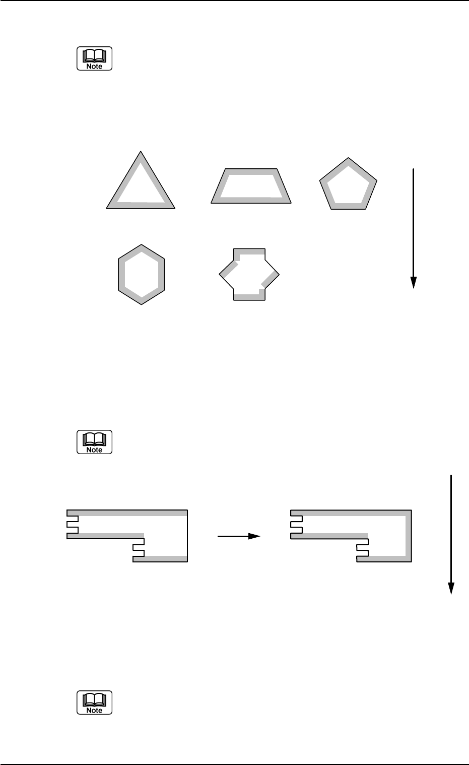
(b) Up to 6 linear edges (3 to 6) must be specified.
(a) The more edges are defined, the higher accuracy can be expected.
However, longer processing time will be required in proportion to the
specified number of edges.
(b) The figures show the linear edge Nos.
Example:
1
2
3
1
2
3
4
1
2
3
4
5
1
2
5
4
6
1
2
3
4
5
6
3
Top View of Component
User Direction of Feed
(c) Select linear edges which have interior angles close to 90°, each
formed by a side and the extension of an adjacent side.
At least one edge must be shifted from the other one by 45 to 135° or 225
to 315°
1
2
3
1
2
3
4
Top View of Component
OKNG
User Direction of Feed
(d) Select linear edges which are 2.0 mm or more in length.
An edge must be perfectly straight without any irregularity.
Fig. B110
Fig. B111