OM-1076-001.pdf - 第70页
(1) Corner Data Des Select the setting method for corner data from the following options. Auto : When this is selected, the same parameter (automatically determined as an appropriate one) is set for the four cor- ners of…
(B01_04) Polarity Existence
Set "Enable" or "Disable" to determine whether or not the component
has a polarity (direction).
This data is used for optimization of the pattern program.
Applicable Components:
Applicable for all subjected components
This data is used for optimization of pattern program.
Refer to the instruction manual "Optimization Software" for details.
(B01_05) Corner Data
Set the shape of component corners and dimensions X and Y.
Top View of Component
B01 Shape Data (B01_04), (B01_05)
Fig. B91
Polarity existence Enable
0111-002 2-45 Tg0502-PM-CL
Fig. B92 Edit Window (Example) for Cylindrical Components
Fig. B93
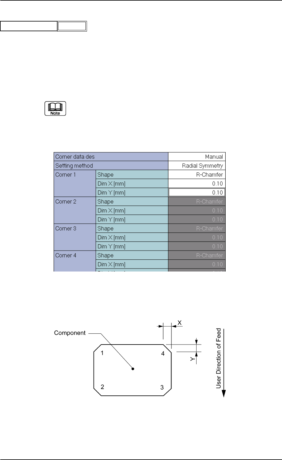
(1) Corner Data Des
Select the setting method for corner data from the following options.
Auto : When this is selected, the same parameter (automatically
determined as an appropriate one) is set for the four cor-
ners of the mold.
Manual : When this is selected, arbitrary parameters can be set.
Select "Manual" when the mold has a particular corner(s), the dimension
of each corner is different, or such corners cannot be recognized well.
Applicable Components: Cylindrical and Square
(2) Setting Method
Select one of the following options to determine how symmetrical the
corners of the component mold are.
Radial Symmetry : When a parameter is set for "Corner 1",
the same parameters are specified for
"Corner 2", "Corner 3", and "Corner 4".
Bilateral Symmetry : When parameters are set for "Corner
1" and "Corner 2", the same parameters
are specified for "Corner 4" and "Cor-
ner 3".
Vertical Symmetry : When parameters are set for "Corner
1" and "Corner 4", the same parameters
are specified for "Corner 2" and "Cor-
ner 3".
Individual Setting : It is required to set parameters individu-
ally for all four corners.
(a) Set a parameter in the "Setting Method" text box only when "Manual"
is selected in the "Corner data des" text box for cylindrical and square
components.
(b) Set a parameter in the "Setting Method" text box only when "Normal
(Rectangle)" is selected in the "Component Type" text box for Deform
(simple) components.
Applicable Components : Cylindrical, Square, and Deform
(Simple)
B01 Shape Data (B01_05)
0111-002 2-46 Tg0502-PM-CL
Manual
Fig. B94
Corner data des
Radial Symmetry
Fig. B95
Setting method
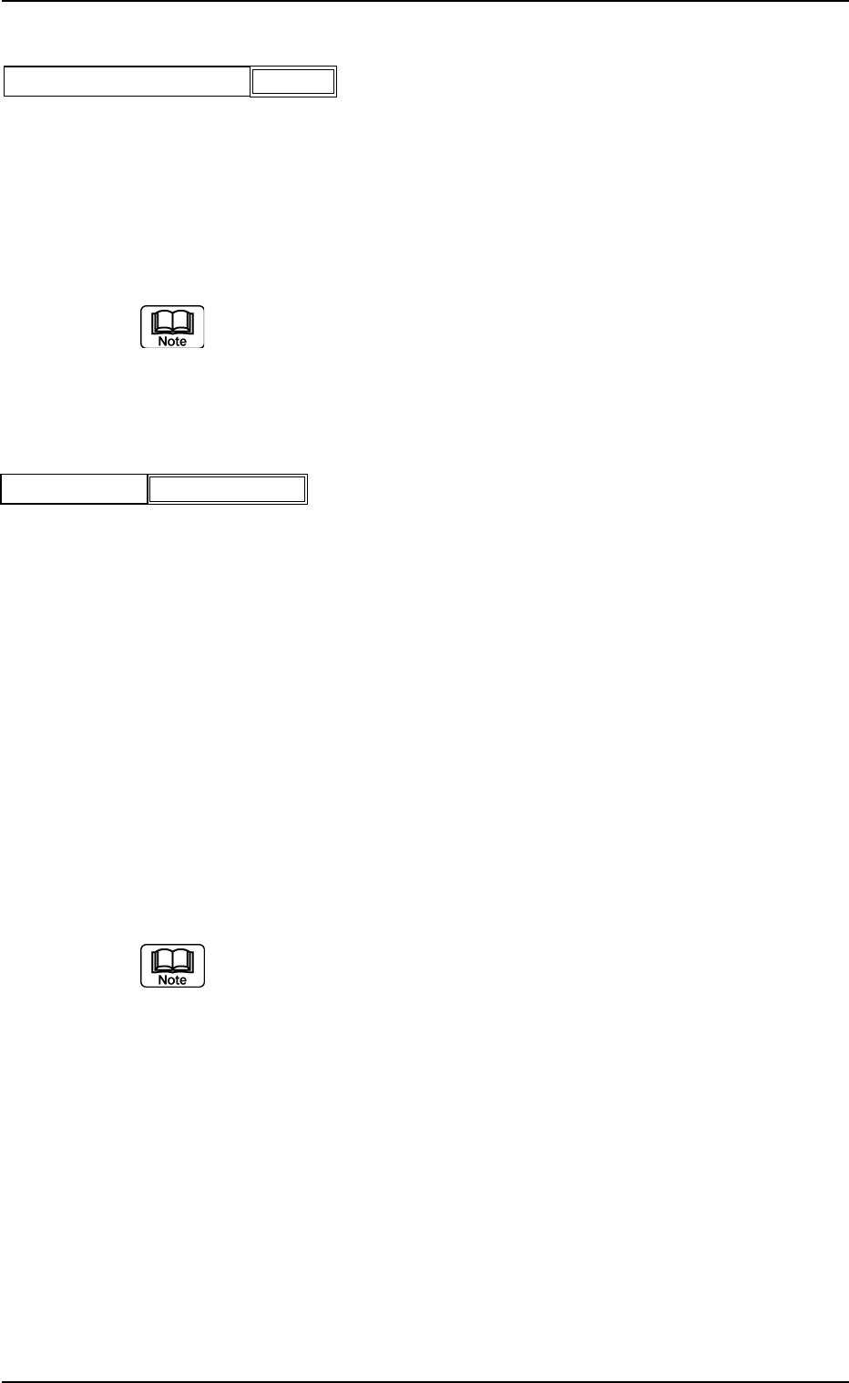
(3) Corner 1, 2, 3, 4 Shape
Set the shapes for "Corner 1", "Corner 2", "Corner 3", and "Corner
4".
Table B12
(a) Corner detection cannot be made when "No Det (Defective)" is set
for the shapes of two or more corners.
(b) When "No Chamfer" is selected, it is not necessary to set any param-
eters for "Dim X" and "Dim Y".
(c) Set a parameter in the "Shape" text box only when "Manual" is se-
lected in the "Corner data des" text box for cylindrical and Square
components.
(d) Set a parameter in the "Shape" text box only when "Normal (Rect-
angle)" is selected in the "Component Type" text box for Deform
(simple) components.
Applicable Components: Cylindrical, Square, and Deform (Simple)
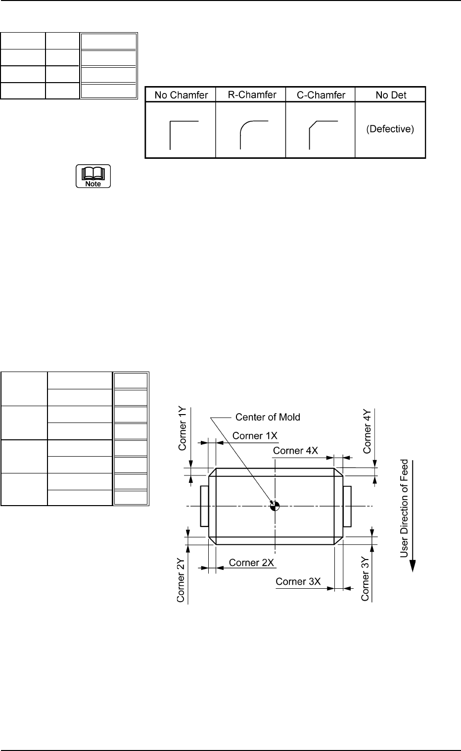
(4) Dim X [mm], Dim Y [mm]
Set dimensions X and Y for "Corner 1", "Corner 2", "Corner 3",
and "Corner 4".
Top View of Component
Unit: mm
Data Input Range
X: 00.00 to 99.99
Y: 00.00 to 99.99
Applicable Components: Cylindrical, Square, and Deform
(Simple)
B01 Shape Data (B01_05)
0206-002 2-47 Tg0502-PM-CL
R-Chamfer
R-Chamfer
R-Chamfer
R-Chamfer
Fig. B96
Shape
Shape
Shape
Shape
Corner 1
Corner 2
Corner 3
Corner 4
0.10
0.10
0.10
0.10
0.10
0.10
0.10
0.10
Fig. B97
Dim X [mm]
Dim Y [mm]
Dim X [mm]
Dim Y [mm]
Dim X [mm]
Dim Y [mm]
Dim X [mm]
Dim Y [mm]
Corner 1
Corner 2
Corner 3
Corner 4
Fig. B98