OM-1076-001.pdf - 第129页
0206-003 2-98 Tg0502-PM-CL (B02_14) Electd Size Detn/Electd Size T ol [mm] Select whether or not the Electrical Contact Size Judgement is per- formed. If it is, select the allowance from the following options. Disable : …
0206-003 2-97 Tg0502-PM-CL
(B02_13) Electd Pos Detn/Electd Pos Tol [mm]
Select whether or not the Electrical Contact Position Judgement is
performed. If it is, select the allowance from the following options.
Disable : Select this when no electrode position determina-
tion is not to be made.
Enable (Auto) : Select this when the electrode position determi-
nation should be made. The default value which
has been automatically set is used for the elec-
trode position tolerance.
Enable (Mnl) : Select this when the electrode position determi-
nation should be made. The arbitrarily set value is
used for the electrode position tolerance.
Unit: mm
Data Input Range: 0 to 9.999
(a) Select this only when "Manual" is set in the "Recognition data set"
data box.
(b) When "Enable (Auto)" is set in the "Electd pos detn" text box, the
value indicated in the "Electd pos tol [mm]" text box is used.
Applicable Components: BGA/CSP
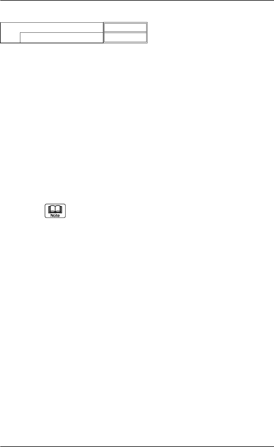
B02 Recognition Data (B02_13)
Fig. B205
Enable (Auto)
0.000
Electd pos detn
Electd pos tol [mm]
0206-003 2-98 Tg0502-PM-CL
(B02_14) Electd Size Detn/Electd Size Tol [mm]
Select whether or not the Electrical Contact Size Judgement is per-
formed. If it is, select the allowance from the following options.
Disable : Select this when the electrode size determination
is not to be made.
Enable (Auto) : Select this when the electrode size determination
should be made. The automatically set default
value is used for the electrode size tolerance.
Enable (Mnl) : Select this when the electrode size determination
should be made. The arbitrary set value is used
for the electrode size tolerance.
Unit: mm
Data Input Range: 0 to 9.999
(a) Select this only when the "Manual" is set in the "Recognition data set"
data box.
(b) When "Enable (Auto)" is set in the "Electd size detn" text box, the
value indicated in the "Electd size tol [mm]" text box is used.
Applicable Components : BGA/CSP
(B02_15) Upper / Lower Surface Detn (Not Available)
Applicable Components : Square
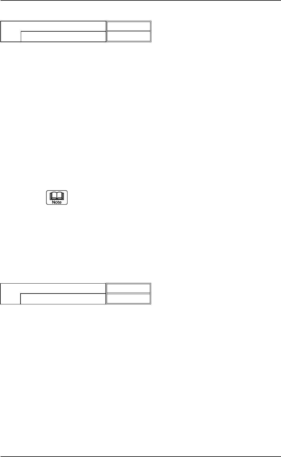
B02 Recognition Data (B02_14), (B02_15)
Fig. B206
Enable (Auto)
0.000
Electd size detn
Electd size tol [mm]
Fig. B207
Enable
Bright
Upper / Lower surface detn
Cmpnt-Mounted surf image
0206-002 2-99 Tg0502-PM-CL
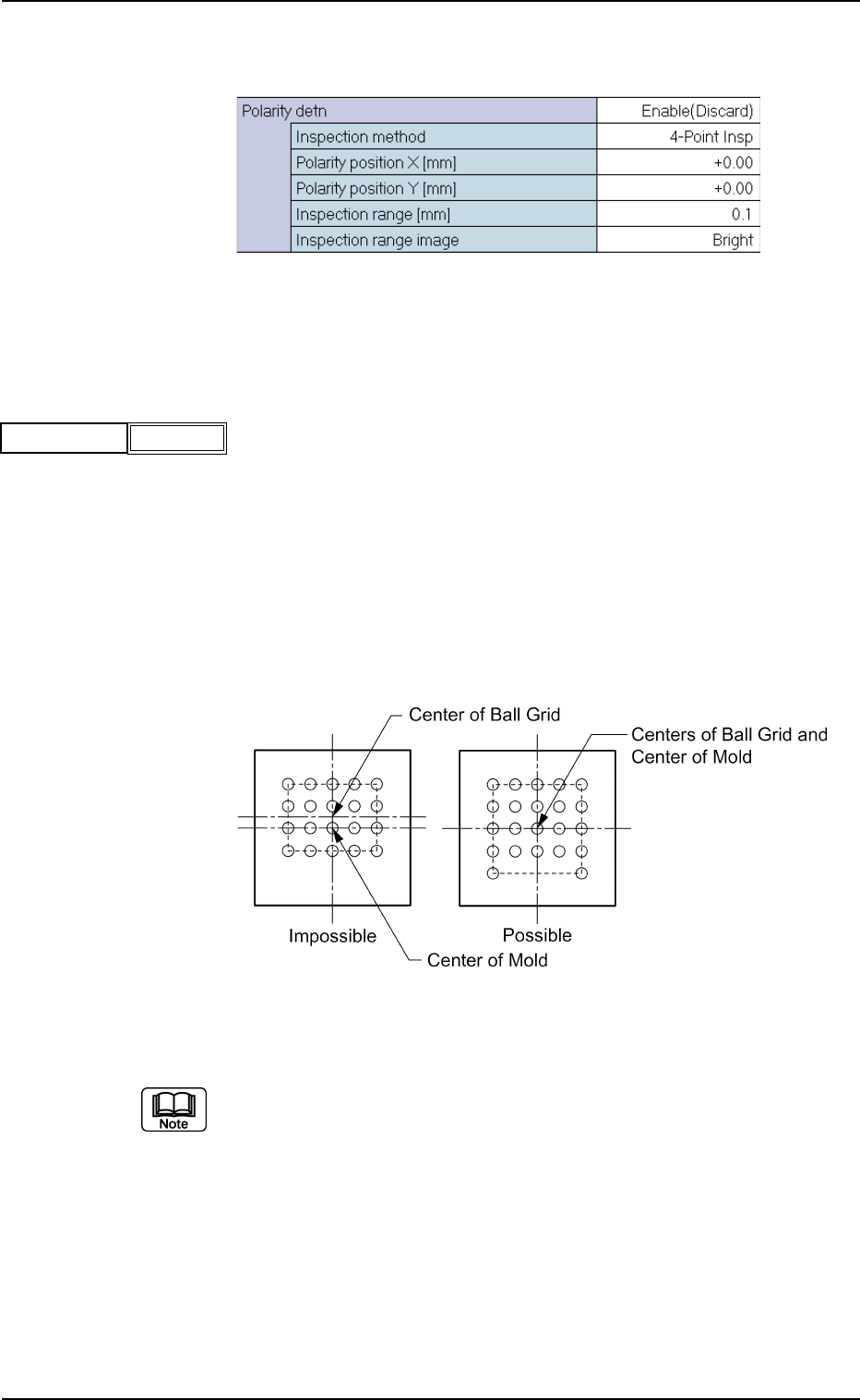
(B02_16) Polarity detn Data
Set the determination way for the component polarity (direction).
Fig. B208 Edit Window (Example)
Applicable Components : BGA/CSP
(1) Polarity detn
Select one of the following options to ascertain whether or not the
polarity determination function should be implemented.
Disable : Select when the polarity determination function is
not implemented.
Enable (Discard) : Select when the polarity has been checked and
found to be different, and is to be determined as
an error.
Enable (Placement) : Select when the recognition function is re-performed
according to the determined polarity after the po-
larity is checked and determined.
Top View of Component
Fig. B210
(a) When "Enable (Placement)" is selected, the recognition processing
time becomes twice or more than usual.
(b) When it is required to check whether or not a component has a polar-
ity (when components are not fed in the specified direction), "Enable
(Discard)" or "Enable (Placement)" must be set in the text box. The
machine performs the recognition operation after checking the polar-
ity.
(c) The following requirements must be met when "Enable (Discard)" or
"Enable (Placement)" is selected.
• With BGA/CSP components, the center of the ball grid should agree
with the center of the mold.
Fig. B209
Polarity detn
Disable
B02 Recognition Data (B02_16)