OM-1076-001.pdf - 第53页
(1) T ype Select one of the following options as a type of a component carrier . Paper Embossed Adhesive Vibratory Stick T ray No types other than the above are used in TIM-X series. (2) Direction Select one of the follo…
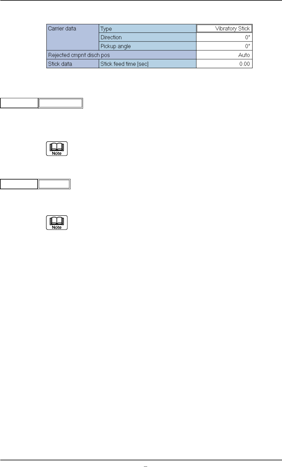
(11) Rejected Cmput Disch Pos
Select one of the following options to designate the position from which
the component must be discharged when a component cannot be
placed due to a component recognition error.
Auto, Recycle Conveyor, Reject Box (Large)
In normal cases, select "Auto".
Select "Recycle Conveyor" only when the machine is equipped with the
recycle component conveyor (option).
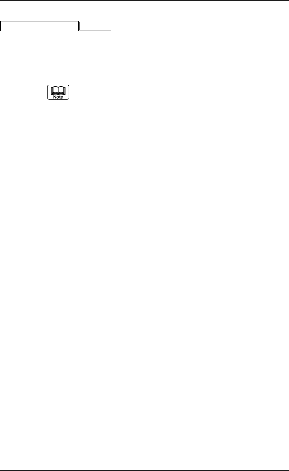
A03 Carrier Data (A03_01)
0206-003 2-31 Tg0502-PM-CL
Auto
Rejected cmpnt disch pos
Fig.B60
(1) Type
Select one of the following options as a type of a component carrier.
Paper Embossed Adhesive Vibratory Stick Tray
No types other than the above are used in TIM-X series.
(2) Direction
Select one of the following options to designate the component feed-
ing direction.
0° 45° 90° 135° 180° 225° 270° 315°
(a) In normal cases, select "0".
(b) The set parameters are used to specify the angular rotation (dimen-
sional values in X and Y directions) of a component for component
recognition.
A03 Carrier Data (A03_02)
(A03_02) Carrier Data (Vibratory Stick Feeder)
Fig. B61
0206-003 2-32
Tg0502-PM-CL
Vibratory Stick
Type
0
Direction
Fig.B63
Fig.B62
A03 Carrier Data (A03_02)
0206-002 2-32-1 Tg0502-PM-CL
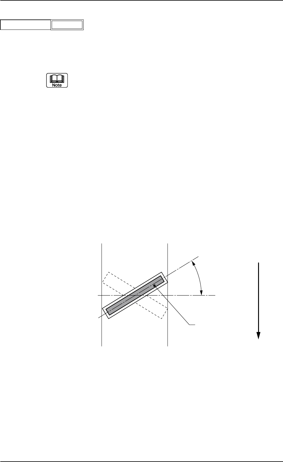
(3) Pick up Angle
Set the angle at which the nozzle should be rotated before a com-
ponent is picked up.
Unit: ° (degree)
Data Input Range: −359° to +359°
(a) Use the set parameter when the rectangular nozzle must be oriented
in the longitudinal direction of a component. (In normal cases, set "+
0°".)
(b) When a value other than "0" (zero) is set in the data box, the dimen-
sions as component shape data (X, Y,..) are determined according to
the component posture (packaged posture) for component recogni-
tion.
(c) Set a value with "+" sign to implement the pick-up operation with a
nozzle pre-rotated counterclockwise.
(d) The nozzle is pre-rotated to the angle entered in this box and picks
up a component. When the component recognition is performed, the
nozzle is rotated back to "0" (zero) degree. The component posture
(the orientation of the component positioned by the nozzle rotated
back to "0" (zero) degree) must be set as a placement angle (pack-
age posture) in the pattern program.
Example: Shown below is a component packaged on the skew.
Fig. B65
−359
Pick up Angle
Fig.B64
Pick-Up Angle
Component
(Connector)
Top View of Component
User Direction of Feeder