OM-1076-001.pdf - 第65页
(2) T (Thickness) [mm], t (Thickness) [mm], Ut (Thickness) [mm] Set the thickness of the component. T (Thickness) : Thickness between Component Placement and Uppermost Surfaces t (Thickness) : Thickness between Component…
B01 Shape Data (B01_02)
0107-001 2-40 Tg0502-PM-CL
Data Input Range:
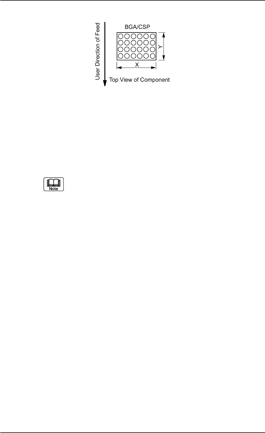
X: 0.01 to 150.00
Y: 0.01 to 150.00
Applicable Components : Cylindrical, Square, Deform (Simple), IC
(Simple), Connector (Simple), Other
Leaded (Simple), and BGA/CSP
Set a parameter in the "Y" text box only when "Normal (Rectangle)" is
selected in the "Cmpnt Type" text box for deform (simple) components.
Set a parameter only in the "X (diameter)" text box when "Round" is se-
lected in the "Component Type" text box.
Area Array
Fig. B81
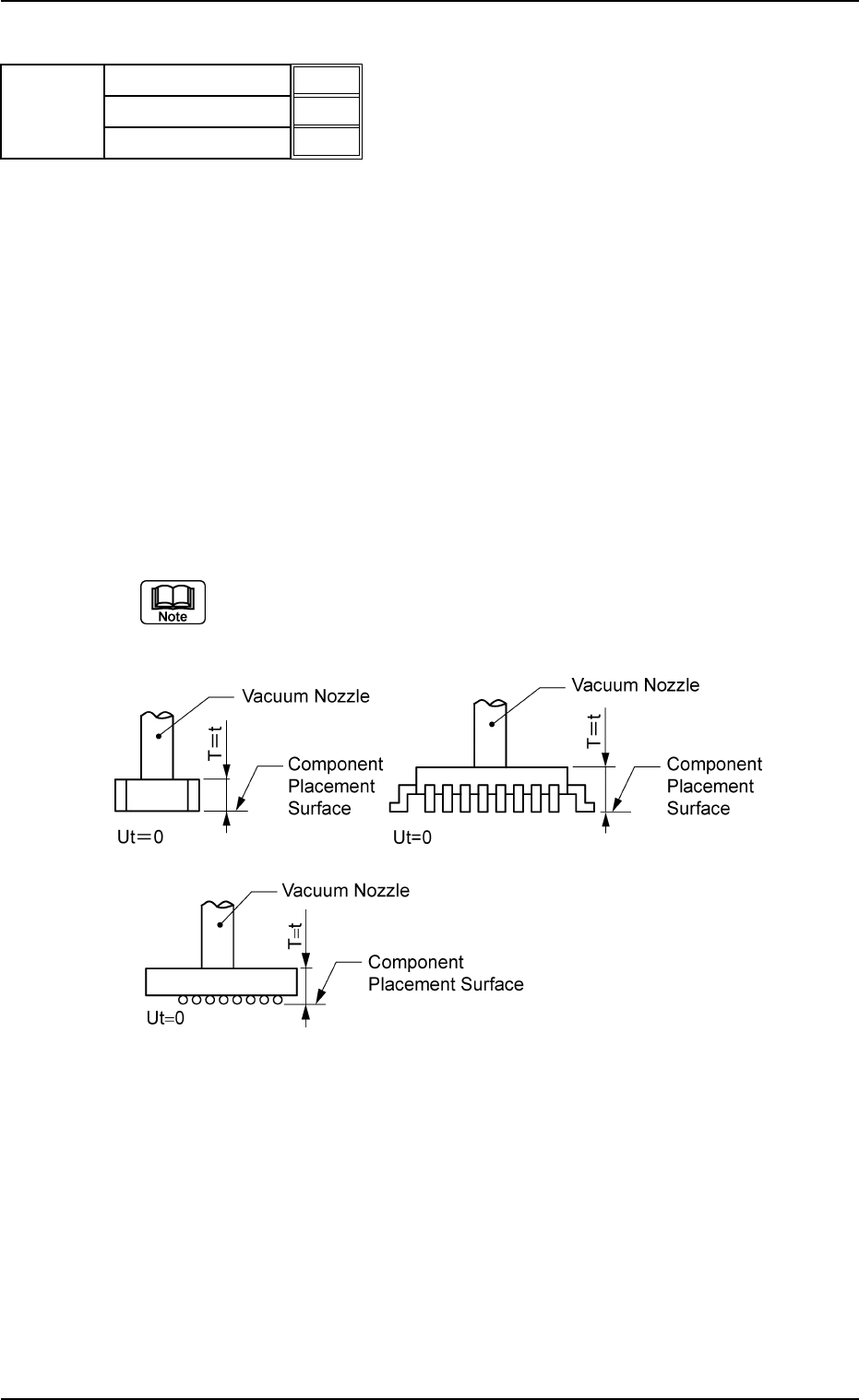
(2) T (Thickness) [mm], t (Thickness) [mm], Ut (Thickness) [mm]
Set the thickness of the component.
T (Thickness) : Thickness between Component Placement and
Uppermost Surfaces
t (Thickness) : Thickness between Component Placement and
Nozzle Pickup Surfaces
Ut (Thickness): Thickness between Component Lowermost and
Placement Surfaces
Unit: mm
Data Input Range
T (Thickness) : 0.01 to 50.00
t (Thickness) : 0.01 to 50.00
Ut (Thickness): 00.00 to 50.00
Applicable Components:
Applicable for all subjected components
(a) Example : T = t
Side View
B01 Shape Data (B01_02)
0206-003 2-41 Tg0502-PM-CL
T (Thickness) [mm]
t (Thickness) [mm]
Ut (Thickness) [mm]
5.70
5.70
0.00
Fig. B82
Mold size
Fig. B83
B01 Shape Data (B01_02)
0107-001 2-42 Tg0502-PM-CL
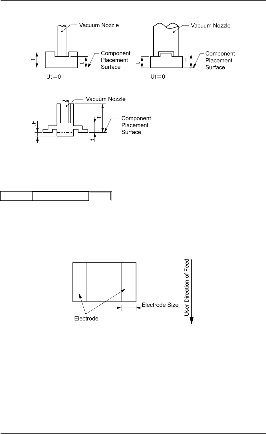
(b) Example: T ≠ t
Side View
(3) Elctd Size [mm]
Set the width of the component's electrode.
This data is used exclusively for front lighting recognition.
Unit: mm
Data Input Range: 0.00 to 99.99
Applicable Component: Square
Fig. B85
0.10
Elctd Size [mm]
Mold Size
Fig. B84
Fig. B86