OM-1076-001.pdf - 第45页
01 11-002 2-26 Tg0502-PM-CL A02 Control Data (A02_09) (A02_09) Error Process 1 When no component can be picked up (Missing components), the machine stops in an error condition according to the number of errors. Set a par…
A02 Control Data (A02_08)
0107-001 2-25 Tg0502-PM-CL
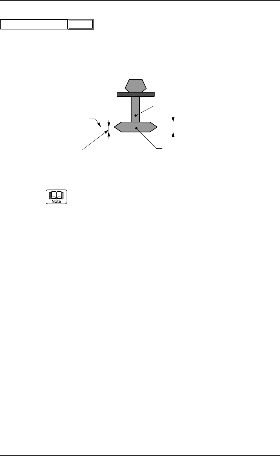
(A02_08) Focus Adjustment [mm]
Set the focus level when a component is recognized.
Unit: mm
Data Input Range: −99.99 to +99.99
(a) Actual operation range may be regulated (differ from the set values)
due to the control of the machine.
(b) In normal cases, the height level for component recognition is deter-
mined according to the parameter set in the "t" data box of the label
"Mold size". However, when a spot regarded as a target to be recog-
nized deviates from the focus point due to the shape of a component,
the set parameter can be used to correct the deviation.
(c) When the recognition target deviates from the focus point as shown
in the figure, enter the dimension (A) with "+" sign in the data box.
When a value with "+" sign is entered, the head will descend further
(as much as the set value) than the normal stroke and the photo-
image of the component is taken for component recognition. When
the parameter set in the "t" data box of the label "Mold size" can be
used as the level for component recognition, "0" (zero) must be set in
this data box.
Nozzle
Component Thickness (t)
Component
Side View
A (Focus Adjustment)
Focus Level
Fig.B41
Focus adjustment [mm]
−99.99
Fig. B42
0111-002 2-26 Tg0502-PM-CL
A02 Control Data (A02_09)
(A02_09) Error Process 1
When no component can be picked up (Missing components), the
machine stops in an error condition according to the number of errors.
Set a parameter in this data box to designate the number of continu-
ous component missing errors to be counted in order to stop the ma-
chine in an error condition.
Data Input Range: 1 to 9
1 : The machine stops in an error condition after no component (rec-
ognition error) is detected once.
2 : The machine stops in an error condition after no component (rec-
ognition error) is detected continuously twice on the same feeder.
n : The machine stops in an error condition after no component (rec-
ognition error) is detected continuously "n" times on the same
feeder.
(a) Recommended Data
Components packaged in 8 mm Tape : 2
Components packaged in 12 mm or Wider Tape : 1
Components packaged in Tray or Stick Feeder : 1
Pick-up error on the tape of width 12 mm or more in the component
(tray or vibration stick component) might cause malfunction. There-
fore, we recommend stopping the machine when the error is first de-
tected.
(b) When the alternate function is activated, the set parameter becomes
one of the requirements for alternate operation start.
Fig.B43
Error process 1
1
A02 Control Data (A02_10)
0111-002 2-27 Tg0502-PM-CL
(A02_10) Error Process 2
The set parameter is used to monitor continuous pick-up errors (an
error caused continuously with a component being picked up) caused
due to component recognition error. The machine stops in an error
condition according to the number of error times. Set the number of
continuous component recognition errors in this data box.
Data Input Range: 1 to 9
1 : The machine stops in an error condition after a component recog-
nition error is detected once.
2 : The machine stops in an error condition after a component recog-
nition error is detected continuously twice on the same feeder.
n : The machine stops in an error condition after a component recog-
nition error is detected continuously "n" times on the same feeder.
(a) Recommended Data
Tape Component : 9
Components in Tray or Stick Feeder : 1
A pick-up error in the tray or vibration stick component might develop
into successive pick-up errors and cause interference with pick-up
nozzle. Therefore, we recommend stopping the machine when the
error is first detected.
(b) When the alternate function is activated, the set parameter becomes
one of the requirements for the alternate operation start.
Fig.B44
Error process 2
1