OM-1076-001.pdf - 第95页
B01 Shape Data (B01_10) 01 11-002 2-69 Tg0502-PM-CL Fig. B144 Pitch [mm] 01.270 Lead No. 1 Fig. B145 (4) Lead Group Pitch [mm] Set the pitch of the leads that belong to each lead group. The center of the mark is the refe…
B01 Shape Data (B01_10)
0107-001 2-68 Tg0502-PM-CL
Fig. B142
# of Leads [pcs.]
005
Lead
No.
1
Fig. B143
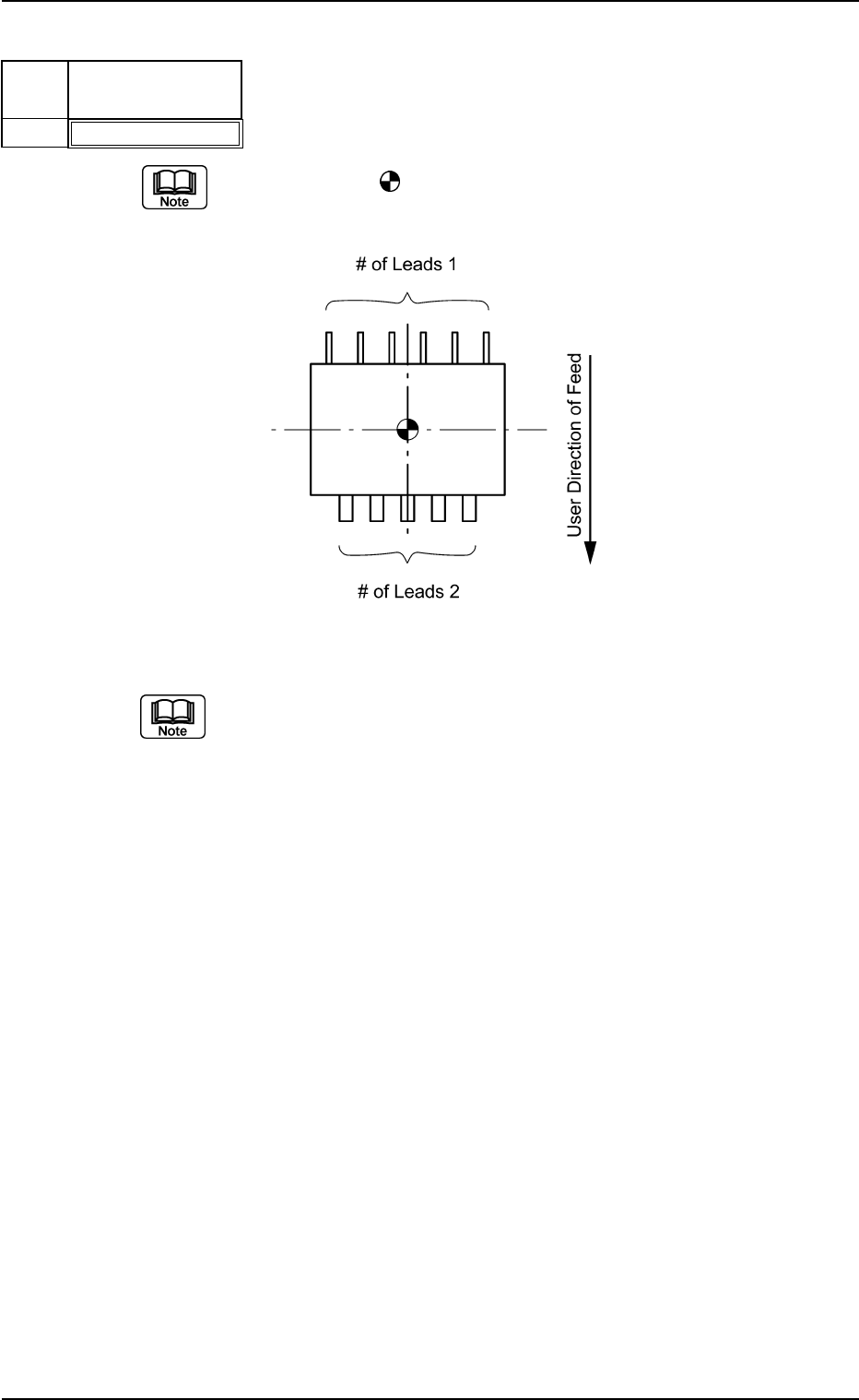
(3) Lead Group # of Leads [pcs.]
Set the number of leads that belong to each lead group.
The center of the
mark is the reference position for outward length
setting.
Top View of Component
The number of missing leads is not included in this number of leads.
Unit: piece
Data Input Range: 1 to 255
Applicable Components : IC (Simple), IC (Complex), Connector
(Simple), Connector (Complex), Other
Leaded (Simple), and Other Leaded
(Complex)
B01 Shape Data (B01_10)
0111-002 2-69 Tg0502-PM-CL
Fig. B144
Pitch [mm]
01.270
Lead
No.
1
Fig. B145
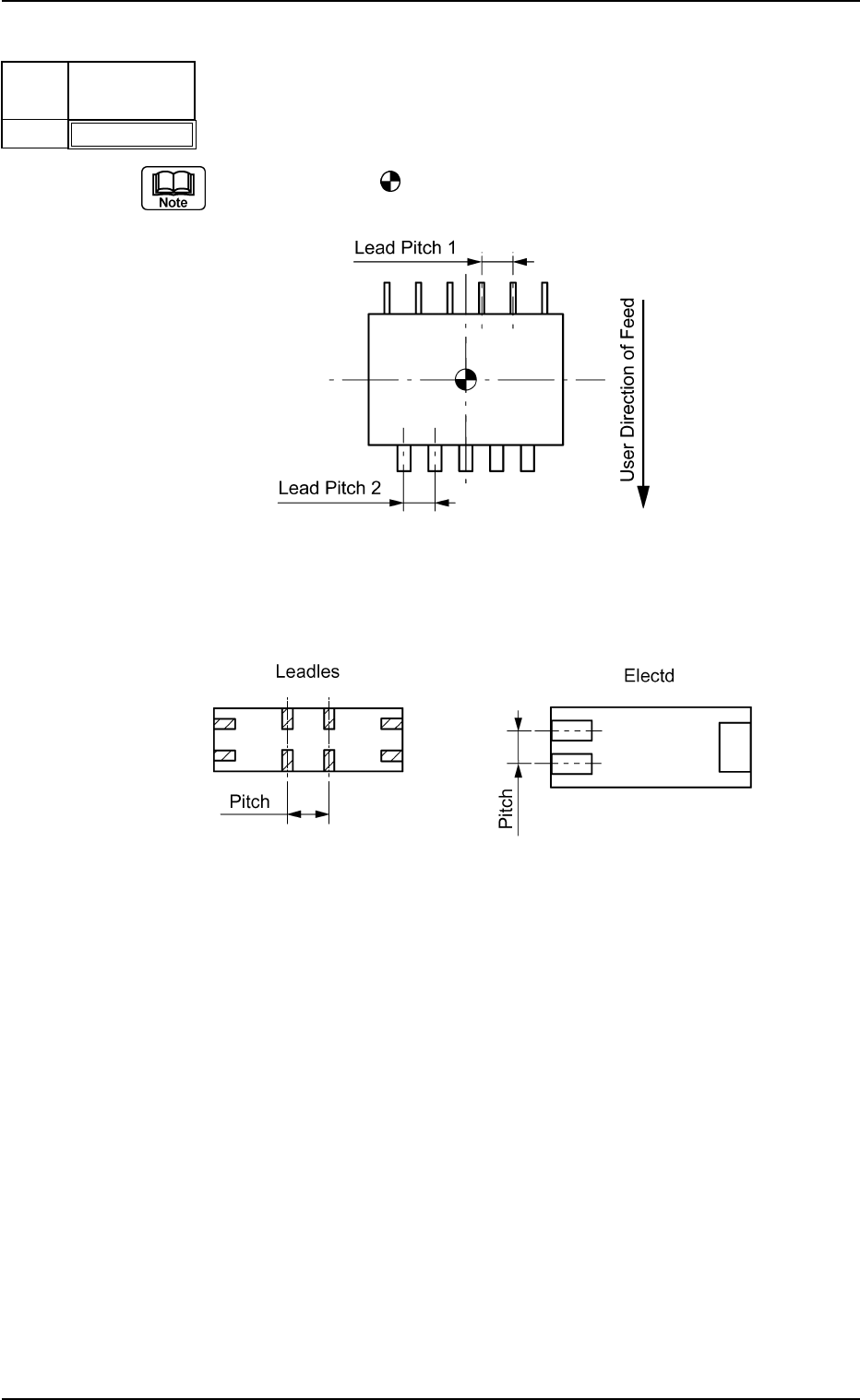
(4) Lead Group Pitch [mm]
Set the pitch of the leads that belong to each lead group.
The center of the
mark is the reference position for outward length
setting.
Top View of Component
Example: Special Case
Bottom View of Component
Unit: mm
Data Input Range: 0 to 99.999
Applicable Components : IC (Simple), IC (Complex), Connector
(Simple), Connector (Complex), Other
Leaded (Simple), and Other Leaded
(Complex)
Fig. B145-1
B01 Shape Data (B01_10)
0107-001 2-70 Tg0502-PM-CL
Fig. B146
Posn (Latl) Det [mm]
+00.000
Lead
No.
1
Fig. B147
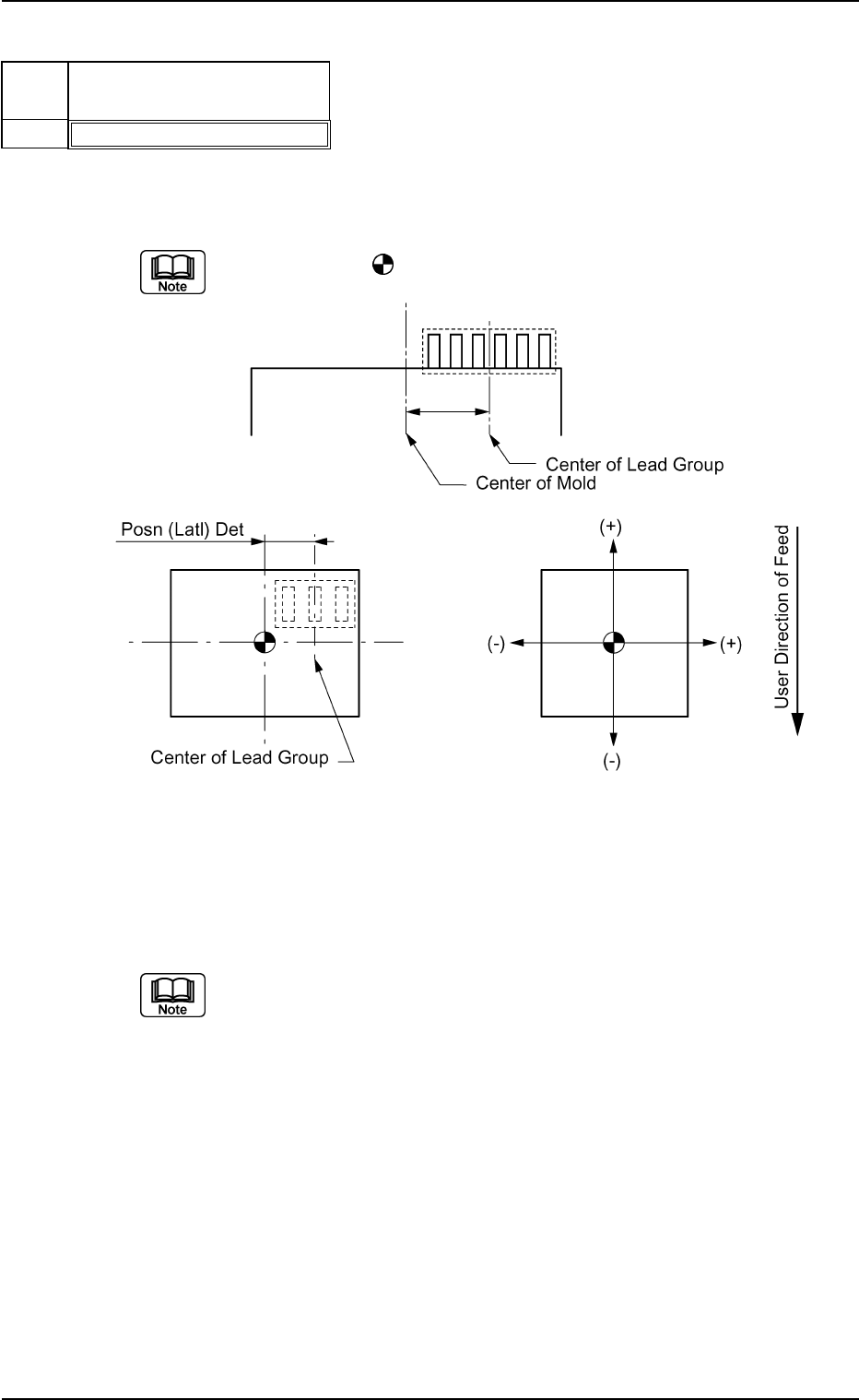
(5) Lead Group Posn (Latl) Det [mm]
Set the distance between the center lines of the mold and a lead group.
"+" and "−" signs must be used as shown in the figure below.
The center of the
mark indicates the center of the mold.
Top View of Component
Unit: mm
Data Input Range: −99.999 to +99.999
Set this only when "Enable" is selected in the "Extended Setting" text box.
Applicable Components : IC (Simple), Connector (Simple), and
Other Leaded (Simple)