OM-1076-001.pdf - 第72页
(a) Set parameters only when "Manual" is selected in the "Corner data des" text box for cylindrical or square components. (b) Set parameters only when "Normal (Rectangle)" is selected in the…
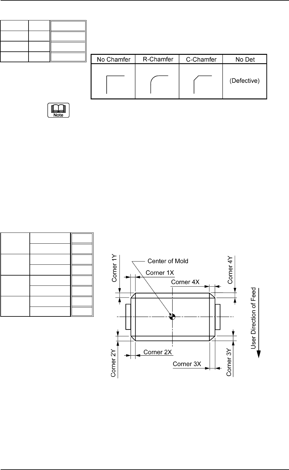
(3) Corner 1, 2, 3, 4 Shape
Set the shapes for "Corner 1", "Corner 2", "Corner 3", and "Corner
4".
Table B12
(a) Corner detection cannot be made when "No Det (Defective)" is set
for the shapes of two or more corners.
(b) When "No Chamfer" is selected, it is not necessary to set any param-
eters for "Dim X" and "Dim Y".
(c) Set a parameter in the "Shape" text box only when "Manual" is se-
lected in the "Corner data des" text box for cylindrical and Square
components.
(d) Set a parameter in the "Shape" text box only when "Normal (Rect-
angle)" is selected in the "Component Type" text box for Deform
(simple) components.
Applicable Components: Cylindrical, Square, and Deform (Simple)
(4) Dim X [mm], Dim Y [mm]
Set dimensions X and Y for "Corner 1", "Corner 2", "Corner 3",
and "Corner 4".
Top View of Component
Unit: mm
Data Input Range
X: 00.00 to 99.99
Y: 00.00 to 99.99
Applicable Components: Cylindrical, Square, and Deform
(Simple)
B01 Shape Data (B01_05)
0206-002 2-47 Tg0502-PM-CL
R-Chamfer
R-Chamfer
R-Chamfer
R-Chamfer
Fig. B96
Shape
Shape
Shape
Shape
Corner 1
Corner 2
Corner 3
Corner 4
0.10
0.10
0.10
0.10
0.10
0.10
0.10
0.10
Fig. B97
Dim X [mm]
Dim Y [mm]
Dim X [mm]
Dim Y [mm]
Dim X [mm]
Dim Y [mm]
Dim X [mm]
Dim Y [mm]
Corner 1
Corner 2
Corner 3
Corner 4
Fig. B98
(a) Set parameters only when "Manual" is selected in the "Corner data
des" text box for cylindrical or square components.
(b) Set parameters only when "Normal (Rectangle)" is selected in the
"Component Type" text box for deform (simple) components.
(c) It is not required to set any parameters when "No Chamfer" is se-
lected in the "Shape" text box.
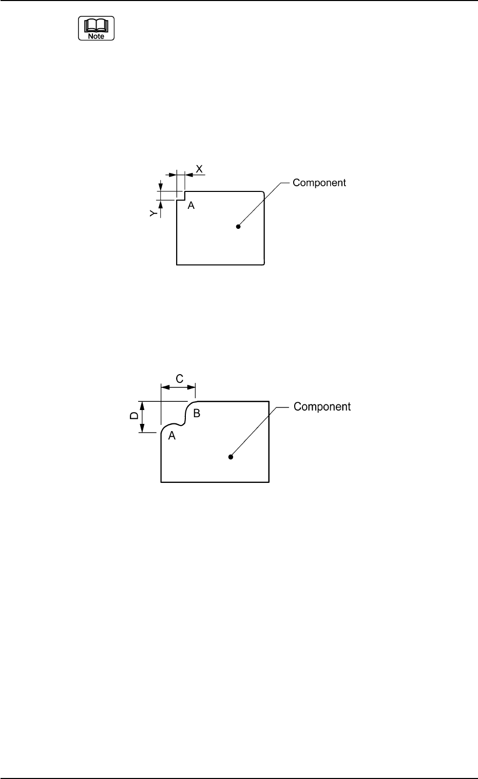
(d) Set parameters for "Dim X" and "Dim Y" even when "No Det" is set for
"Shape" of a corner indicated below as A. In this case, the dimen-
sions of a similar corner are regarded as Dimensions X and Y.
Top View of Component
(e) Set "No Det (Defective)" when a component mold has two similar
corners shown below as A and B. In this case, set the size of C in
"Dim X" and set the size of D in "Dim Y".
Top View of Component
B01 Shape Data (B01_05)
0107-001 2-48 Tg0502-PM-CL
Fig. B99
Fig. B100
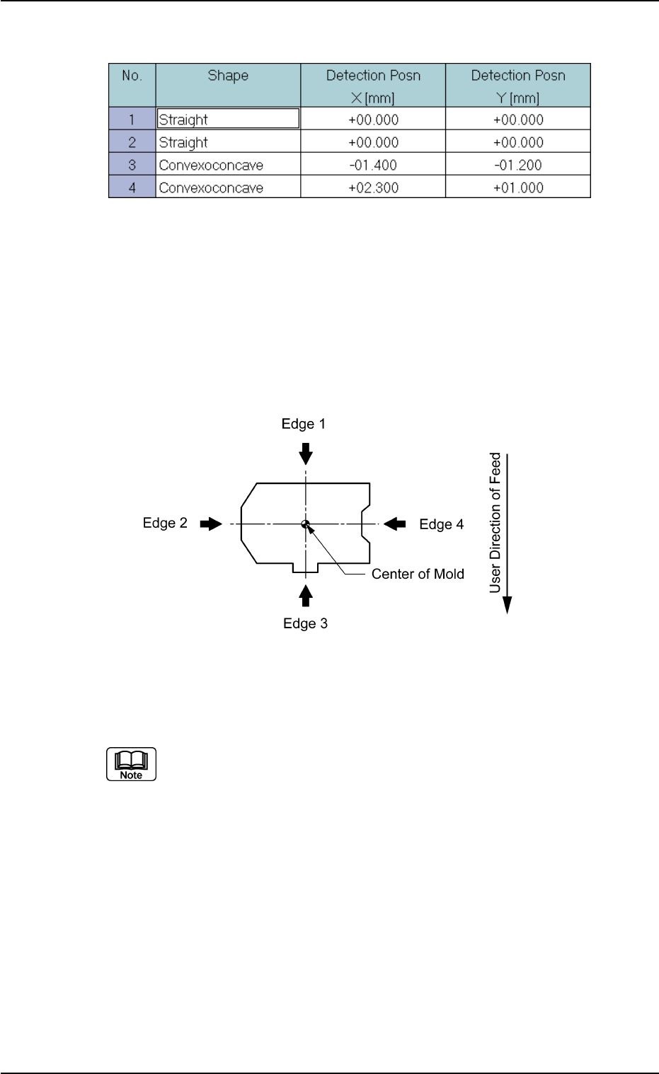
(B01_06) Edge Data
Set edge shapes at each detectable position in the "Shape", "Detec-
tion Posn X", and "Detection Posn Y" for Edges "1", "2", "3", and "4".
Be sure to select two or more edges and set parameters for them as
edge data.
• Edges 1, 2, 3, and 4
The following shows the positional relation of a component based
on the packaged posture.
Top View of Component
Applicable Components: Deform (Simple)
Set parameters only when "Normal (Rectangle)" is selected in the "Cmpnt
Type" text box.
B01 Shape Data (B01_06)
0107-001 2-49 Tg0502-PM-CL
Fig. B101 Edit Window (Example) for Deform (Simple) Components
Fig. B102