OM-1076-001.pdf - 第96页
B01 Shape Data (B01_10) 0107-001 2-70 Tg0502-PM-CL Fig. B146 Posn (Latl) Det [mm] + 00.000 Lead No. 1 Fig. B147 (5) Lead Group Posn (Latl) Det [mm] Set the distance between the center lines of the mold and a lead group. …
B01 Shape Data (B01_10)
0111-002 2-69 Tg0502-PM-CL
Fig. B144
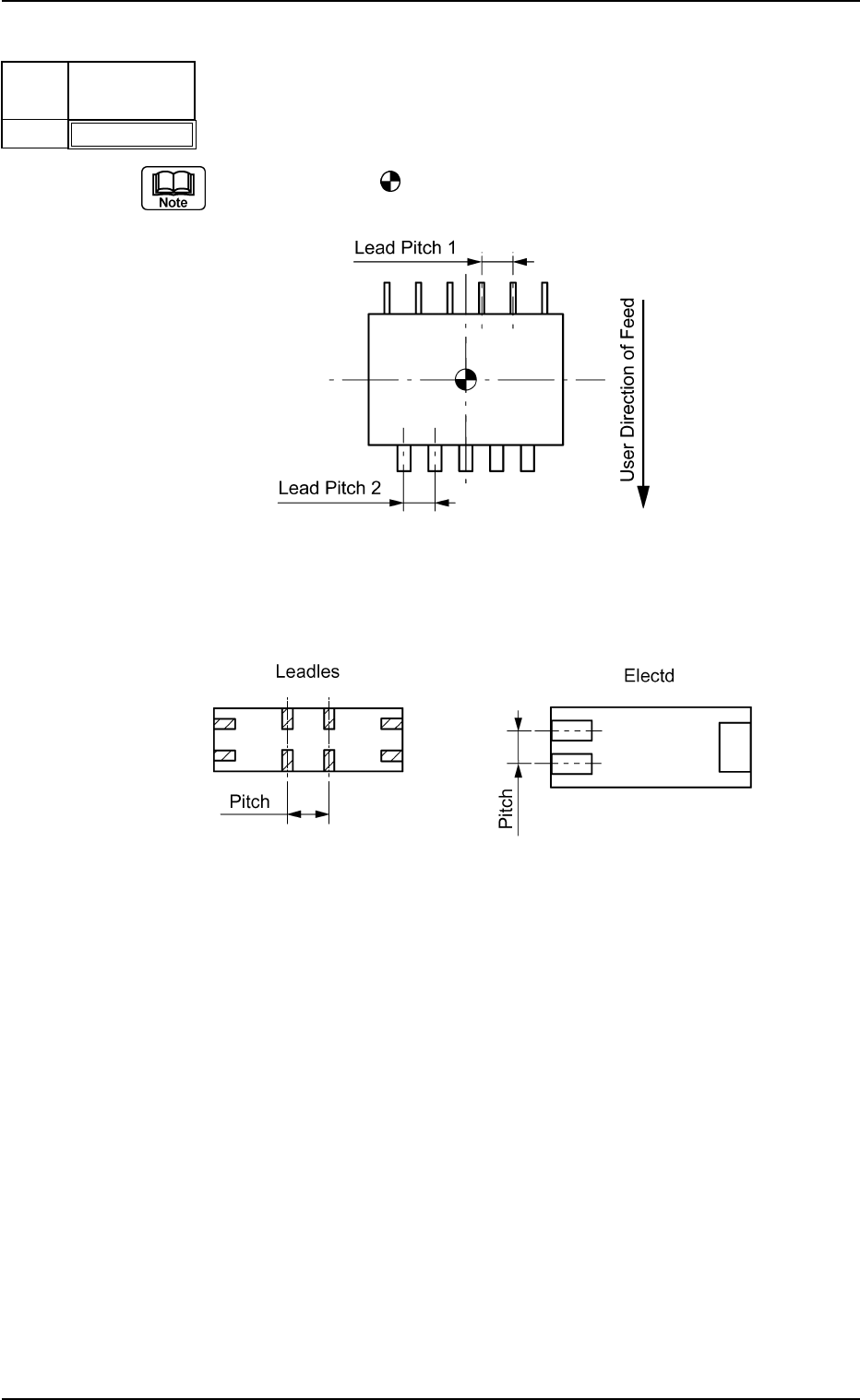
Pitch [mm]
01.270
Lead
No.
1
Fig. B145
(4) Lead Group Pitch [mm]
Set the pitch of the leads that belong to each lead group.
The center of the
mark is the reference position for outward length
setting.
Top View of Component
Example: Special Case
Bottom View of Component
Unit: mm
Data Input Range: 0 to 99.999
Applicable Components : IC (Simple), IC (Complex), Connector
(Simple), Connector (Complex), Other
Leaded (Simple), and Other Leaded
(Complex)
Fig. B145-1
B01 Shape Data (B01_10)
0107-001 2-70 Tg0502-PM-CL
Fig. B146
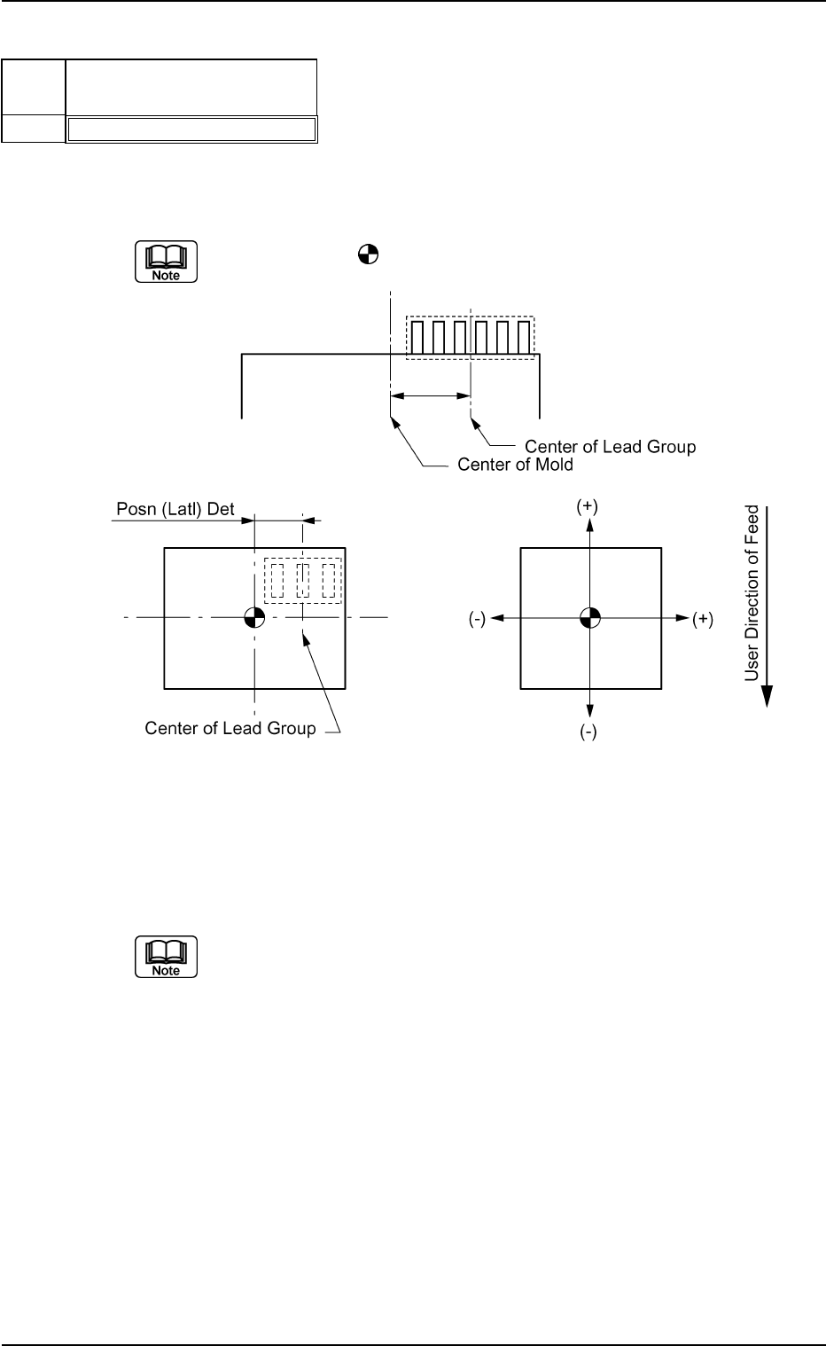
Posn (Latl) Det [mm]
+00.000
Lead
No.
1
Fig. B147
(5) Lead Group Posn (Latl) Det [mm]
Set the distance between the center lines of the mold and a lead group.
"+" and "−" signs must be used as shown in the figure below.
The center of the
mark indicates the center of the mold.
Top View of Component
Unit: mm
Data Input Range: −99.999 to +99.999
Set this only when "Enable" is selected in the "Extended Setting" text box.
Applicable Components : IC (Simple), Connector (Simple), and
Other Leaded (Simple)
B01 Shape Data (B01_10)
0107-001 2-71 Tg0502-PM-CL
Fig. B148
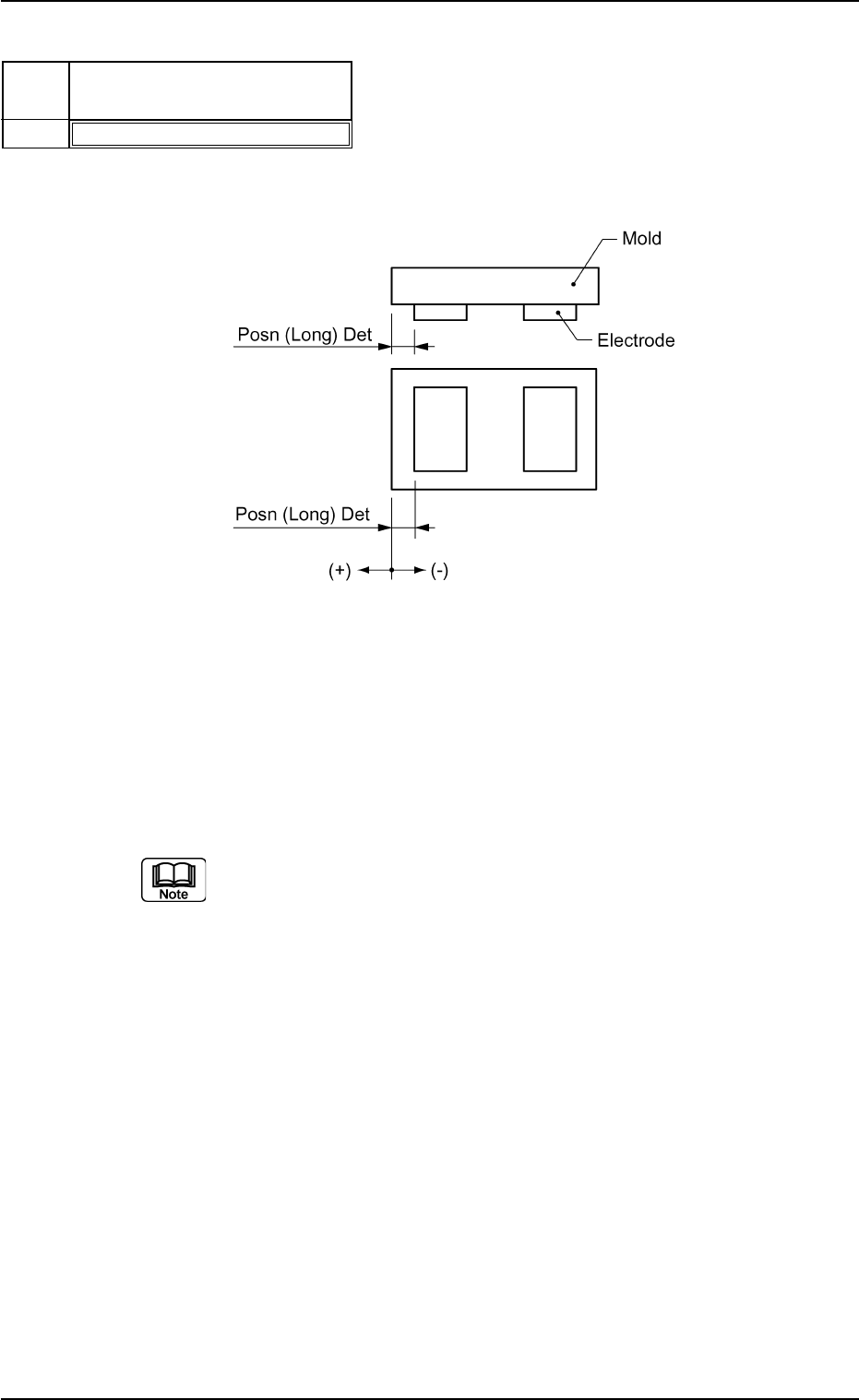
Posn (Long) Det [mm]
+04.105
Lead
No.
1
Fig. B149
(6) Lead Group Posn (Long) Det [mm]
Set the distance between the edges of the mold and the lead (elec-
trode).
Unit: mm
Data Input Range: -99.999 to 99.999
Applicable Components: IC (Simple), Connector (Simple), and
Other Leaded (Simple)
(a) To set a parameter in the "Posn (Long) Det" text box, select "Enable"
in the "Extended Setting" text box.
(b) Set a parameter only when "Leadless" is selected in the "Type" text
box for ICs.
A parameter must be set when "Electd" is selected in the "Type" text
box for connectors or other leaded components.
(c) A minus (−) value must be set when the edge of the lead (electrode)
is located inside the edge of the mold.
A plus (+) value must be set when the edge of the lead (electrode) is
protruding from the edge of the mold.