OM-1076-001.pdf - 第49页
(5) T ape Feed Check Select how to set the feeding and returning time from the following two items. Auto : The feeding and returning time is automatically set by the tape width and feed pitch. Manual : "T ape feed t…
(2) Tape Width [mm]
Select one of the following options as a tape width.
8 12 16 24 32 44 56 72
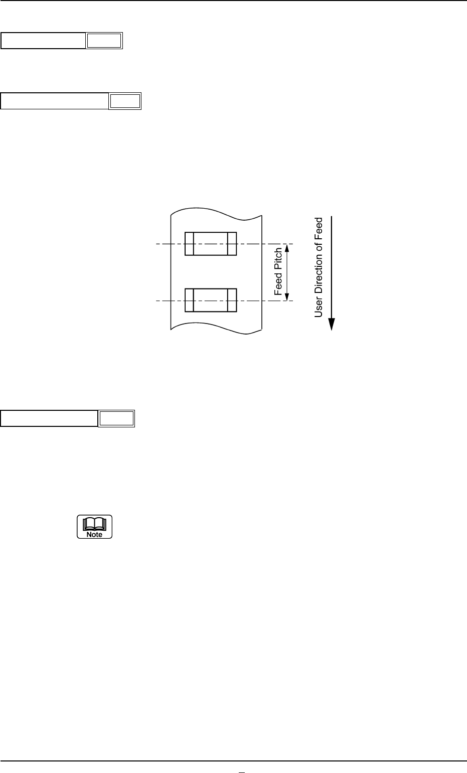
(3) Tape Feed Pitch [mm]
Select one of the following options as a tape feed pitch (a distance
between components).
Unit: mm
Data Input Range: 0 to 99
(4) Tape Feed Counts [times]
Set the number of tape feeding operations of the tape feeder.
Unit: times
Data Input Range: 1 to 9
(a) In the case of a tape feed pitch of 24 mm or more, and if two or more
feeding operations are required, set the number of operations for the
feeder.
(b) In general, for a feeder with a tape feed pitch of 2 to 20 mm, the
number of feeding operations is set to "1" (one).
A03 Carrier Data (A03_01)
0206-003 2-29 Tg0502-PM-CL
Fig. B50
4
Fig. B49
Tape feed pitch [mm]
8
Tape width [mm]
Fig. B48
Fig. B51
Tape feed Counts
1
(5) Tape Feed Check
Select how to set the feeding and returning time from the following
two items.
Auto : The feeding and returning time is automatically set by the tape
width and feed pitch.
Manual : "Tape feed time" and "Tape return time" can be set manually.
(6) Tape Feed Time [sec]
Set the feeding time of the tape feed cylinder.
Unit : Second
Data Input Range : 0.050 to 1.999
When this data is set, set "Tape Feed Check" to "Manual".
A03 Carrier Data (A03_01)
0206-002 2-29-1 Tg0502-PM-CL
Fig. B52
Tape feed check
Manual
Fig. B53
Tape feed time [sec]
0.050
A03 Carrier Data (A03_01)
0206-003 2-30 Tg0502-PM-CL
(7) Tape Return Time [sec]
Set the returning time of the tape feed cylinder.
Unit : Second
Data Input Range : 0.050 to 1.999
When this data is set, set "Tape Feed Check" to "Manual".
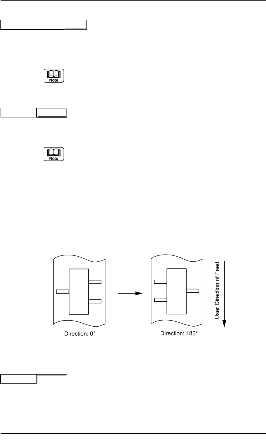
(8) Direction
Select one of the following options as a direction of tape feed.
0° 45° 90° 135° 180° 225° 270° 315°
(a) The direction is determined based on "0° " and shows the angle at
which a component is rotated counterclockwise.
(b) Set "0°" in normal cases (default) and make the component library
data.
(c) It shows the direction for the component when supplied, based on a
position set in the Component Size.
Example: When the component supply direction is changed from (A)
to (B), as shown in the following figure, change the direc-
tion from 0° to 180°. In that event, however, the placement
angle on the pattern program data must also be changed.
(A) (B)
Fig. B56
(9) Q’ty
Set the number of components to be placed in the tape feeder.
Unit : Pcs.
Data Input Range: 1 to 9999
Fig. B54
Tape return time [sec]
0.050
0
Direction
Fig. B55
1000
Q’ty
Fig. B57