OM-1076-001.pdf - 第69页
(B01_04) Polarity Existence Set "Enable" or "Disable" to determine whether or not the component has a polarity (direction). This data is used for optimization of the pattern program. Applicable Compon…
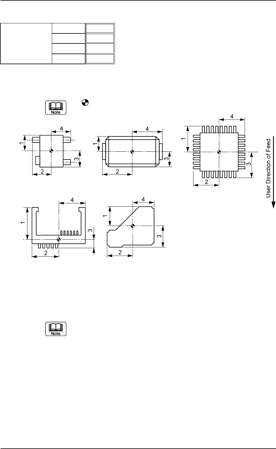
(B01_03) Outward Length 1 [mm], 2 [mm], 3 [mm], 4 [mm]
Set the dimensions between the center of the mold and the outmost
edges.
The
mark indicates the center of the mold.
Top View of Component
Unit: mm
Data Input Range: 0.01 to 150.00
(a) As for "Connector (Complex)" and "Other Leaded (Complex)", "Out-
ward Length 1, 2, 3, 4" and "Gp Ctr Pos (Latl Dir) n" & "Gp Prior Pos
(Long Dir) n" in "Lead Data" must be set based on the same refer-
ence position.
(b) As for the deform (complex) components, the reference position to
set parameters for "Outward Length" must be the same as the refer-
ence position to set parameter "St Coord X and Y" in "Linear Edge
Data".
Applicable Components : Deform (Simple), Deform (Complex), IC
(Simple), IC (Complex), Connector (Simple),
Connector (Complex), Other Leaded
(Simple), and Other Leaded (Complex)
B01 Shape Data (B01_03)
0107-001 2-44 Tg0502-PM-CL
Outward length
1.65
1.85
1.65
1.85
Fig. B89
1 [mm]
2 [mm]
3 [mm]
4 [mm]
Fig. B90
(B01_04) Polarity Existence
Set "Enable" or "Disable" to determine whether or not the component
has a polarity (direction).
This data is used for optimization of the pattern program.
Applicable Components:
Applicable for all subjected components
This data is used for optimization of pattern program.
Refer to the instruction manual "Optimization Software" for details.
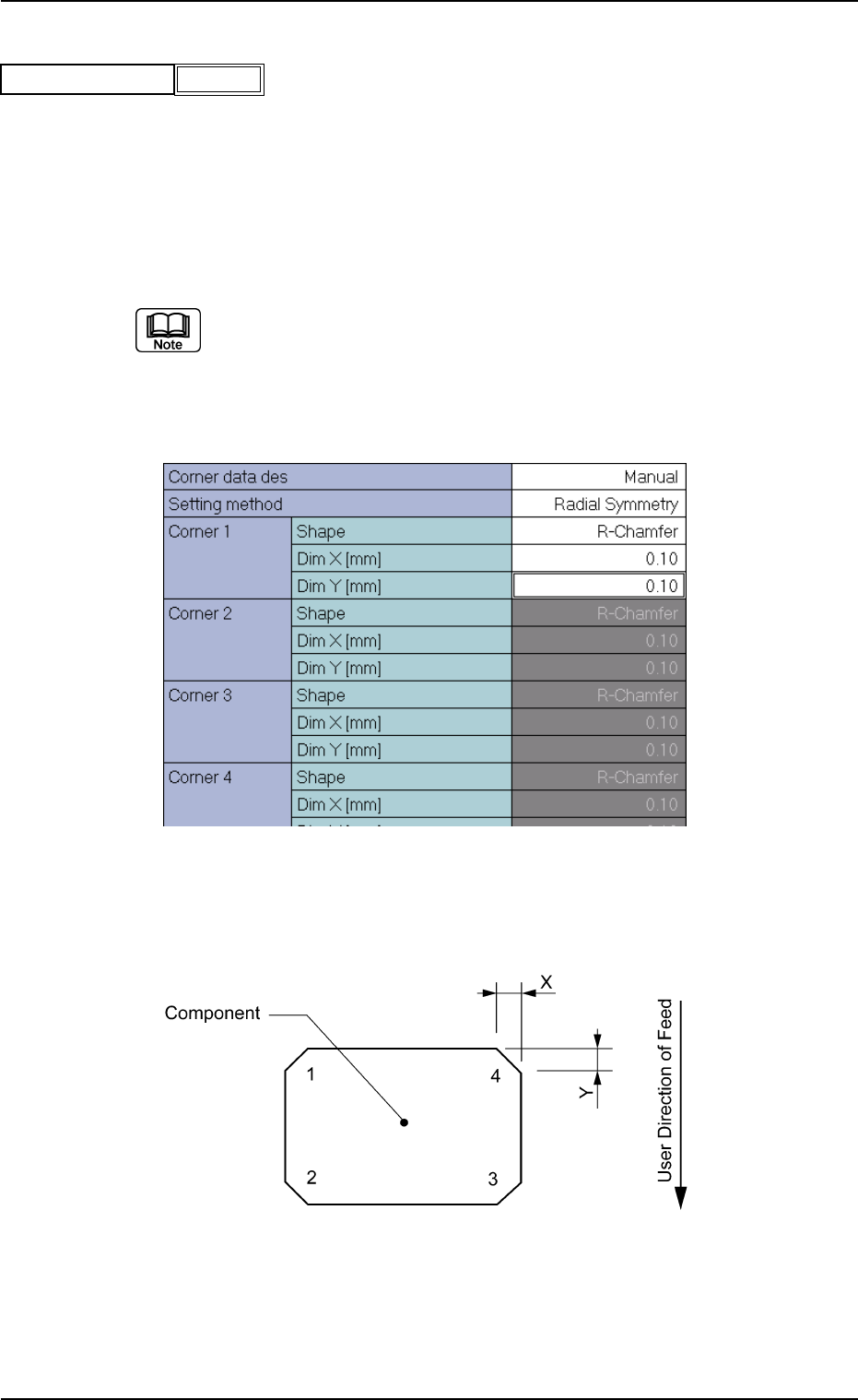
(B01_05) Corner Data
Set the shape of component corners and dimensions X and Y.
Top View of Component
B01 Shape Data (B01_04), (B01_05)
Fig. B91
Polarity existence Enable
0111-002 2-45 Tg0502-PM-CL
Fig. B92 Edit Window (Example) for Cylindrical Components
Fig. B93
(1) Corner Data Des
Select the setting method for corner data from the following options.
Auto : When this is selected, the same parameter (automatically
determined as an appropriate one) is set for the four cor-
ners of the mold.
Manual : When this is selected, arbitrary parameters can be set.
Select "Manual" when the mold has a particular corner(s), the dimension
of each corner is different, or such corners cannot be recognized well.
Applicable Components: Cylindrical and Square
(2) Setting Method
Select one of the following options to determine how symmetrical the
corners of the component mold are.
Radial Symmetry : When a parameter is set for "Corner 1",
the same parameters are specified for
"Corner 2", "Corner 3", and "Corner 4".
Bilateral Symmetry : When parameters are set for "Corner
1" and "Corner 2", the same parameters
are specified for "Corner 4" and "Cor-
ner 3".
Vertical Symmetry : When parameters are set for "Corner
1" and "Corner 4", the same parameters
are specified for "Corner 2" and "Cor-
ner 3".
Individual Setting : It is required to set parameters individu-
ally for all four corners.
(a) Set a parameter in the "Setting Method" text box only when "Manual"
is selected in the "Corner data des" text box for cylindrical and square
components.
(b) Set a parameter in the "Setting Method" text box only when "Normal
(Rectangle)" is selected in the "Component Type" text box for Deform
(simple) components.
Applicable Components : Cylindrical, Square, and Deform
(Simple)
B01 Shape Data (B01_05)
0111-002 2-46 Tg0502-PM-CL
Manual
Fig. B94
Corner data des
Radial Symmetry
Fig. B95
Setting method