OM-1076-001.pdf - 第35页
(9) Pl Descent Dclr 2 [%] Set a parameter to designate the rate of the speed reduction when the X/Y beam descends to the bottom of the remaining stroke (down to the placement lower limit specified in the "Dclr 2 Str…
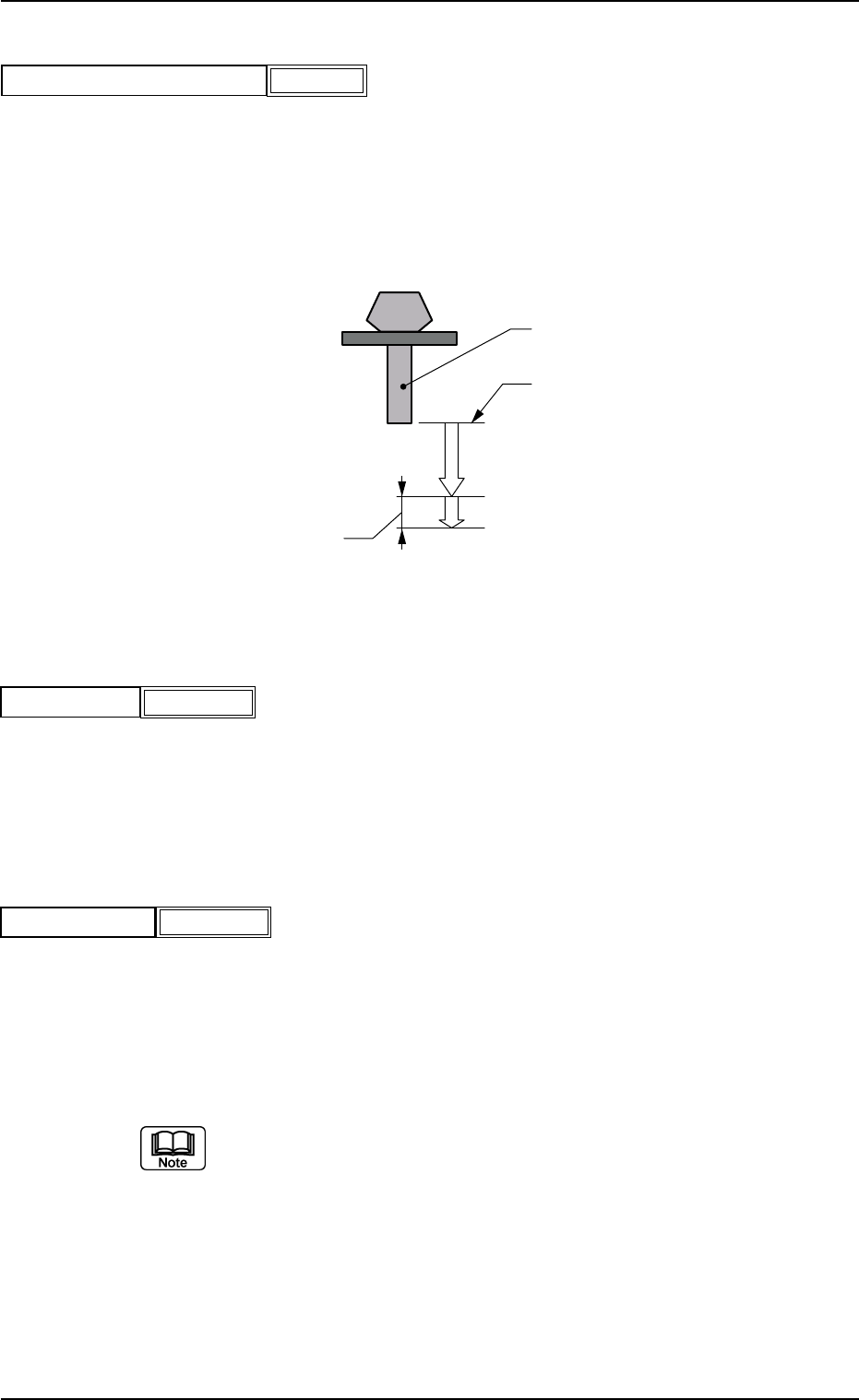
Nozzle
Reflection of "Pu Descent Dclr 1"
Reflection of "Pu Descent Dclr 2"
"Pu Descent Dclr 2 Stroke"
Pass Line
(Lower or Upper Pass Line)
Side View
A02 Control Data (A02_01)
0206-002 2-16 Tg0502-PM-CL
(6) Pu Descent Dclr 2 Stroke [mm]
Set the stroke in the data box, so that the X/Y beam descends at a
very slow speed for the duration of the stroke (speed reduction speci-
fied in the "Pu descent dclr 2").
Unit: mm
Data Input Range: 1.00 to 5.00
Pu descent dclr 2 stroke [mm]
1.00
Fig.B16
(7) Pu Ascent
Select one of the following options to designate the rate of the head
ascending speed reduction after the component pick-up.
Full Speed 10% Decr 20% Decr 30% Decr 40% Decr
50% Decr 60% Decr 70% Decr 80% Decr 90% Decr
(8) Pl Descent Dclr 1
Select one of the following options to designate the rate of the speed
reduction when the head descending motion is started for component
pick-up.
Full Speed 10% Decr 20% Decr 30% Decr 40% Decr
50% Decr 60% Decr 70% Decr 80% Decr 90% Decr
(a) In the normal case the descending motion starts from the pass line
(lower or upper pass line).
When a parameter is set in the "Dclr 2 Stroke" data box, the X/Y
beam descends to the position of the stroke.
(b) The lower pass line is the lowest level for the X/Y beam movement
when the thickness of a previously-placed component (already-placed
component) is 6.5 mm or less.
The upper pass line is the lowest level of the X/Y beam movement
when the thickness of a previously-placed component is more than
6.5 mm. (Only in the placement PCB area)
Fig.B18
Pu ascent Full Speed
Fig.B19
Pl descent dclr 1 Full Speed
Fig. B17
(9) Pl Descent Dclr 2 [%]
Set a parameter to designate the rate of the speed reduction when
the X/Y beam descends to the bottom of the remaining stroke (down
to the placement lower limit specified in the "Dclr 2 Stroke" data box).
Unit: %
Data Input Range: 0 to 99
(a) By making the X/Y beam descend at a very low speed, to the bottom
of the remaining stroke (down to the placement lower limit), a deli-
cate component placement can be made in stable conditions. The
set parameter becomes valid only when it is larger than the rate set in
the "Dclr 1" data box.
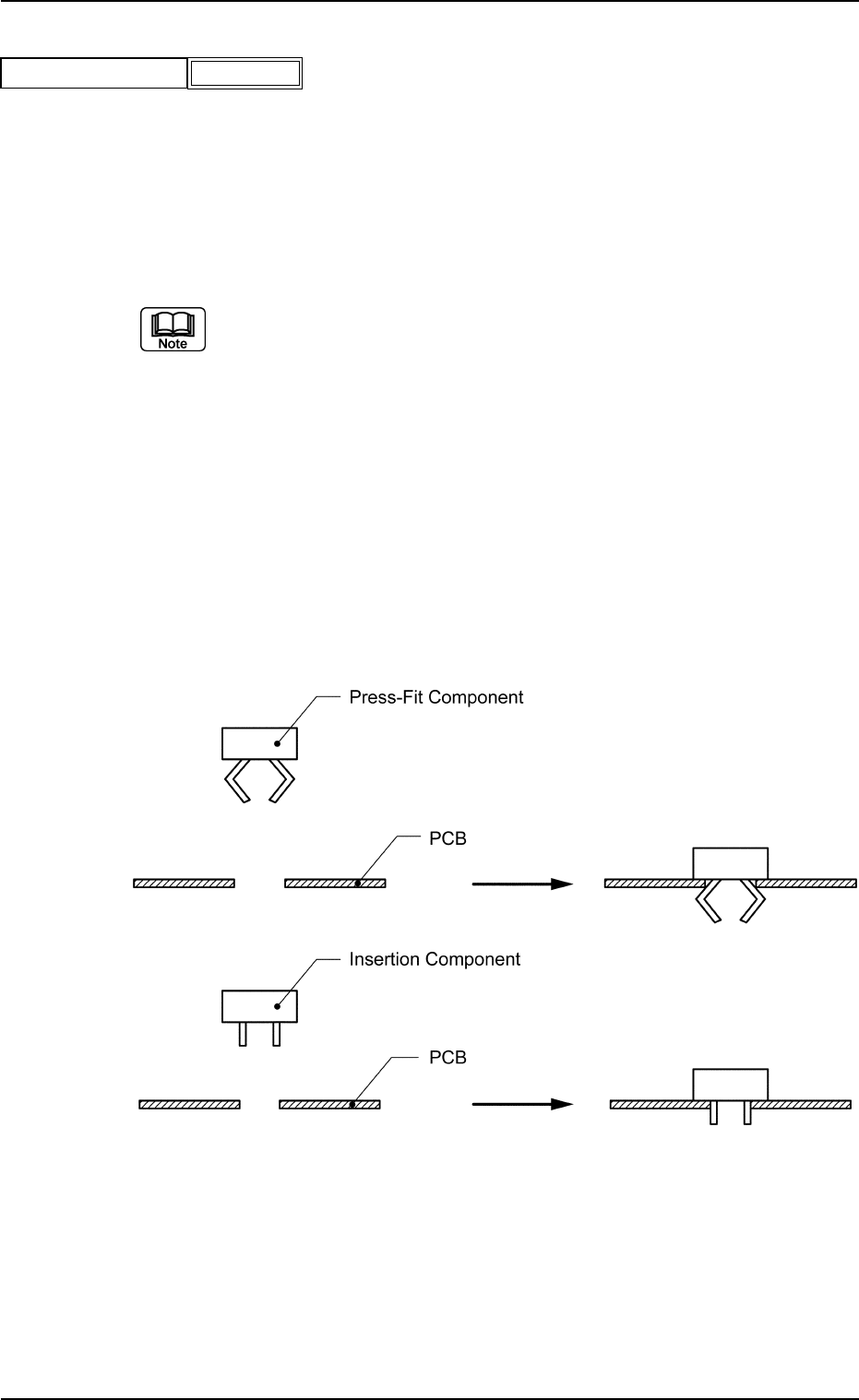
(b) When press-fit or insertion components must be placed, it is neces-
sary to reduce the descending speed so that while such components
are being placed there will be no strong impulse to the PCBs. How-
ever, if the speed is reduced from the start of the descending motion
up to the component placement, then the duration of the placement
motion will be prolonged. In this case, the time can be shortened by
using only "Dclr 2", with the parameter in the "Dclr 1" data box set to
"Full Speed".
A02 Control Data (A02_01)
0206-002 2-17 Tg0502-PM-CL
Fig.B20
Pl descent dclr 2 [%] 0
(c) In the following case the X/Y beam descends in accordance with the
parameter in the "Pl descent dclr 1" and without making a two-step
speed reduction.
Fig. B21
(10) Pl Descent Dclr 2 Stroke [mm]
Set a parameter to designate the stroke in the data box so that the X/
Y beam descends along with the stoke and at a very slow speed (speed
reduction specified in the "Pl descent dclr 2").
Unit: mm
Data Input Range: 1.00 to 5.00
A02 Control Data (A02_01)
0206-002 2-18 Tg0502-PM-CL
Fig.B22
Pl descent dclr 2 stroke [mm]
1.00
Use this function when a press-fit or insertion component must be placed.
(11) Pl Ascent
Select one of the following options to designate the rate of the head
ascending speed reduction after the component placement.
Full Speed 10% Decr 20% Decr 30% Decr 40% Decr
50% Decr 60% Decr 70% Decr 80% Decr 90% Decr
(12) Nozzle Rotation
Select one of the following options to designate the rate of nozzle
rotation speed reduction when a component is picked up.
Full Speed 10% Decr 20% Decr 30% Decr 40% Decr
50% Decr 60% Decr 70% Decr 80% Decr 90% Decr
Fig.B25
Nozzle rotation Full Speed
Fig.B24
Pl ascent Full Speed
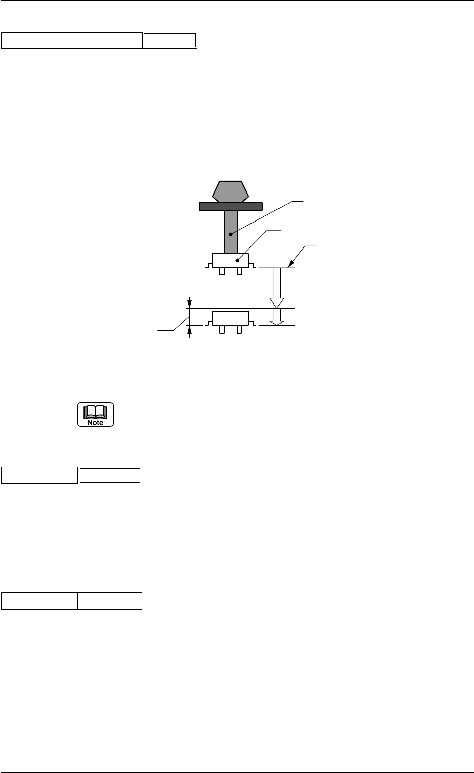
Nozzle
Component
Reflection of "Pl Descent Dclr 1"
Reflection of "Pl Descent Dclr 2"
"Pl Descent Dclr 2 Stroke"
Pass Line
(Lower or Upper Pass Line)
Side View
Fig. B23