OM-1076-001.pdf - 第170页
0206-002 4-13 Tg0502-PM-CL 3.2 Area Array Components Fig. D24 3.2 Area Array Components 3.2.1 BGA/CSP Components Measure the dimensions (*1 through *10) in the figure below . When a component has several electrode groups…
3.1 Leadless Components
0107-001 4-12 Tg0502-PM-CL
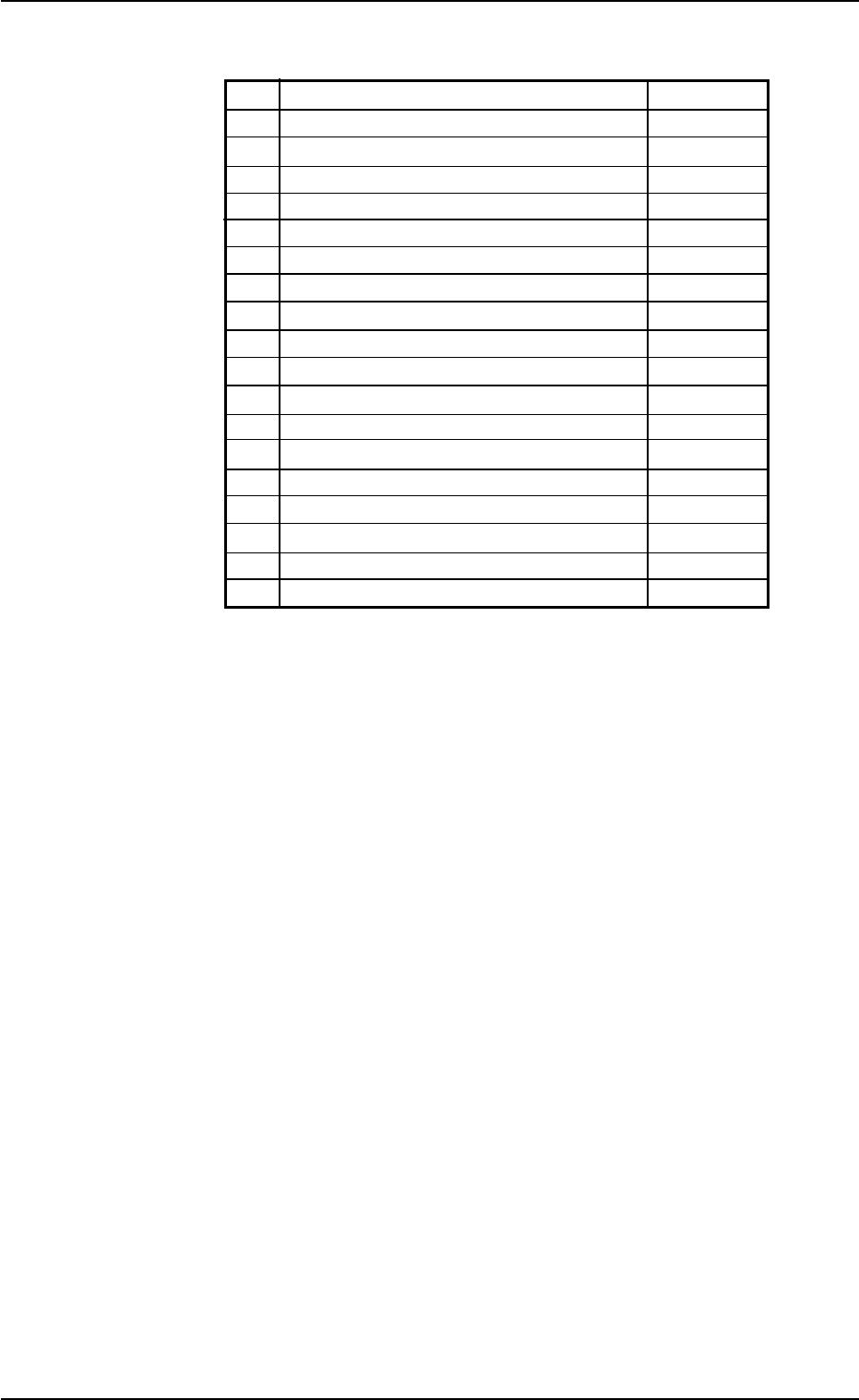
Individual Data Sheet (Deform: Simple Shape)
Minimum Unit: 0.01 mm
*1 Mold Size X (Horizontal)
*2 Mold Size Y (Vertical)
*3 Mold Size t (Thickness) [T (Thickness)]
*4 Outward Length 1
*5 Outward Length 2
*6 Outward Length 3
*7 Outward Length 4
*8 Corner 1 Dim X
*9 Corner 1 Dim Y
*10 Corner 2 Dim X
*11 Corner 2 Dim Y
*12 Corner 3 Dim X
*13 Corner 3 Dim Y
*14 Corner 4 Dim X
*15 Corner 4 Dim Y
*16 Edge Data 1 Detection Posn X
*17 Edge Data 1 Detection Posn Y
*18 Edge Data 2 Detection Posn X
*19 Edge Data 2 Detection Posn Y
0206-002 4-13 Tg0502-PM-CL
3.2 Area Array Components
Fig. D24
3.2 Area Array Components
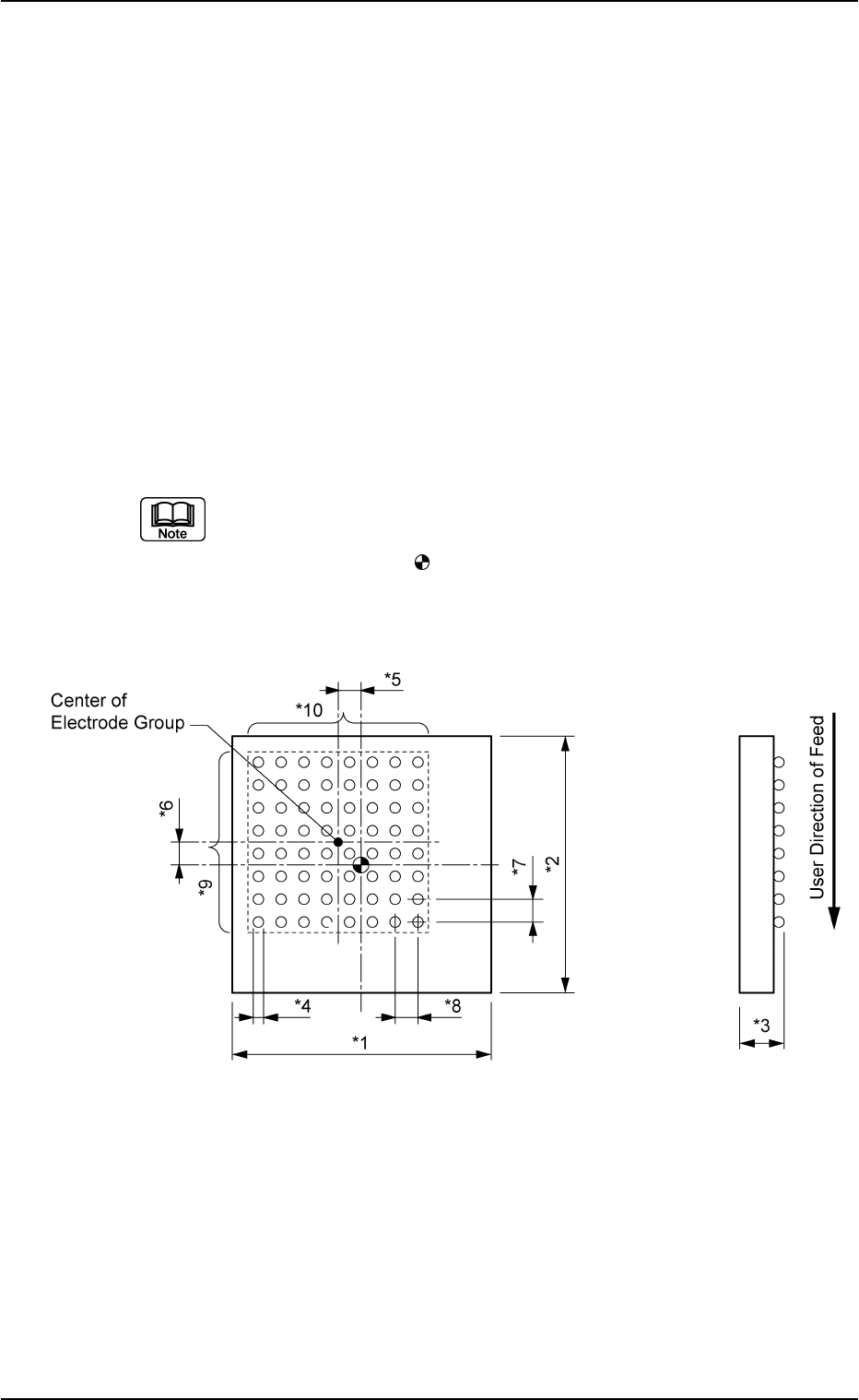
3.2.1 BGA/CSP Components
Measure the dimensions (*1 through *10) in the figure below.
When a component has several electrode groups, set "Enable" in the
"Extended setting" text box and measure the dimensions (*5 through
*10) for Electrode Groups 2 through 6.
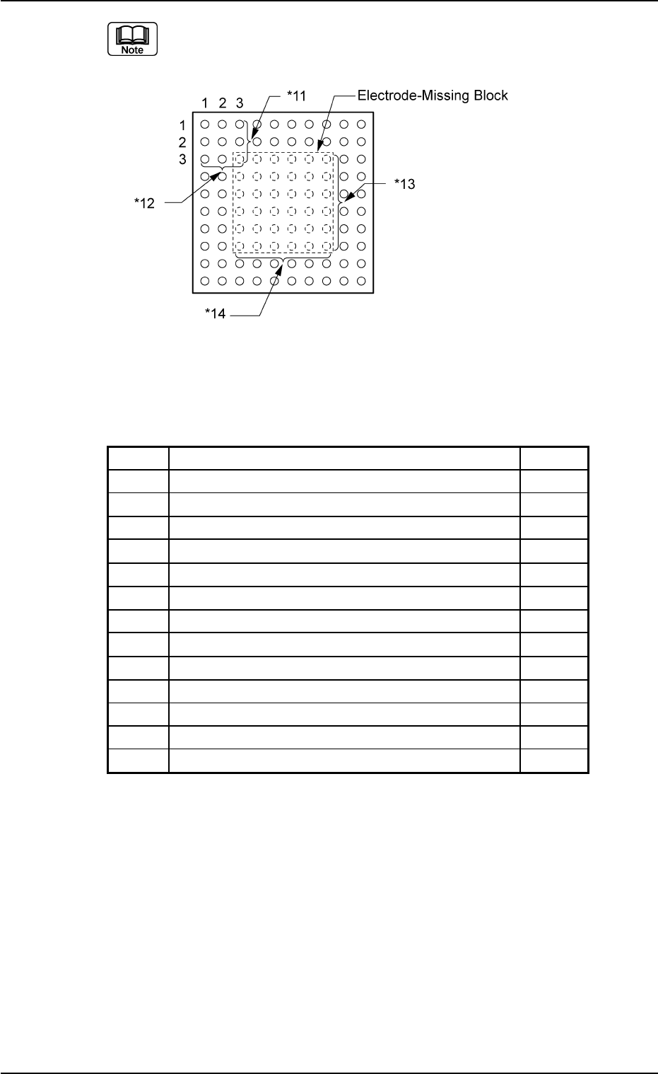
As for components with missing electrodes, set "Enable" in the "Ex-
tended setting" text box and the number of missing blocks in the "# of
Missing Electrodes" text box. After that, measure the dimensions (*11
through *14) in the figure.
When there are several missing blocks, measure the dimensions (*11
through *14) for Missing Electrodes 2, 3, and so on.
(Up to 40 blocks can be specified as electrode-missing blocks.)
(a) The figure shows the top view (no ball side) of the component and is
an example of "# of Electrode Groups = 1".
(b) The center of the mark is the reference point of the component.
(In normal cases, the reference point is located at the center of the
mold.)
0206-002 4-14 Tg0502-PM-CL
3.2 Area Array Components
Minimum Unit: 0.001 mm
*1 Mold size X [mm]
*2 Mold size Y [mm]
*3 Mold size t [mm] (thickness) [T [mm] (thickness)]
*4 Elctd Type #1 Dim 1 [mm]
*5 Grp Posn X [mm] of Grp No. 1
*6 Grp Posn Y [mm] of Grp No. 1
*7 Row Pitch [mm] of Grp No. 1
*8 Col Pitch [mm] of Grp No. 1
*9 # Of Rows [pcs.] of Grp No. 1
*10 # Of Cols [pcs.] of Grp No. 1
*11 Missing Stg Row of Elctd Grp No. 1
*12 Missing Stg Col of Elctd Grp No. 1
*13 # Of Missing Rows [pcs.] of Elctd Grp No. 1
*14 # Of Missing Cols [pcs.] of Elctd Grp No. 1
Fig. D25
Individual Data Sheet (BGA/CSP)
The figure shows the top view (no electrode side) of the component.