OM-1076-001.pdf - 第120页
: This represents an option for a recognition system. Be sure to select one option. : This is an option for a recognition system when "Auto" is selected. One option is selected indispensably . T able B20 B02 Re…

0206-001 2-88-4 Tg0502-PM-CL
B02 Recognition Data (B02_04)
Lead (Standard 2)
: This is the lead detection method for front light-
ing for the smaller component (components for
small view) and components with smaller num-
ber of leads.
Example: Transistor, Diode and SOP, etc.It is
only applicable for the components
with black mold Leads smaller than
standard can be detected. However,
each lead has to shine indepen-
dently. (Molded leads or leads which
appear stuck together with their ad-
jacent leads can not be detected).
Lead (Special) : Round, eccentric, and rectangular electric con-
tacts and holes are detected.
Example: Shield Case, etc.
Multiple Pin Leads (Standard):
: This is a lead detection system for components
with multiple leads (flat-package type).
It is possible to perform processing at higher
speed than the multiple pin leads (general pur-
pose).
This system can be applied only to the compo-
nents having black molds.
Example: General ICs (SOP, QFP, PLCC, etc.)
Multiple Pin Leads (Standard 2)
: Speed processing higher than that of Flat Pack-
aged Components (Standard) is available.
It is applicable only for components with black
mold.
Example: General ICs (SOP, QFP, PLCC, etc)
This function is exclusive to all recognition with
back lighting or front lighting.
Multiple Pin Leads (General Purpose):
This is a general-purpose lead detection sys-
tem.
Example: Connectors, etc.
Grid Pattern : The electrodes consisting of meshes (grids),
and the bumps, etc., can be detected.
: This represents an option for a recognition system. Be sure
to select one option.
: This is an option for a recognition system when "Auto" is
selected. One option is selected indispensably.
Table B20
B02 Recognition Data (B02_04)
0111-002 2-89 Tg0502-PM-CL
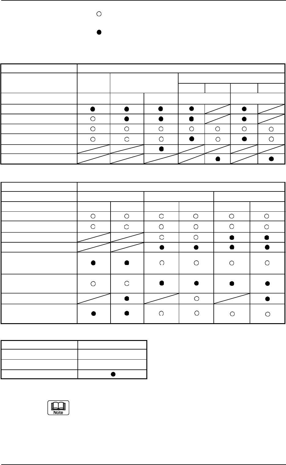
Applicable Components : Applicable for all subjected components
The above parameter can be specified only when "Manual" is selected in
the "Recognition data set" text box.
Leadless Component
Cylindrical Square Deform
Simple Complex Simple Complex
Back Ltg Back Ltg Front Ltg Back Ltg Front Ltg
Component Shapes
Component Type
Recognition System
Corner
Edge
CG (Angle Detected)
CG
(No Angle)
Edge
(
Rectangle
)
Line
Table B22
Component Shapes Area Array
Component Type BGA/CSP
Recognition System Front Ltg
Grid Pattern
Leaded Component
IC Connector Other Leaded
Back Ltg Front Ltg Back Ltg Front Ltg Back Ltg Front Ltg
Table B21
Component Shapes
Component Type
Recognition System
CG (Angle Detected)
CG
(No Angle )
Lead
Lead (Special)
Multi-pin Lead
(Standard )
Multi-pin Lead
(General )
Lead (Standard 2)
Multi-pin Lead
(Standard 2)
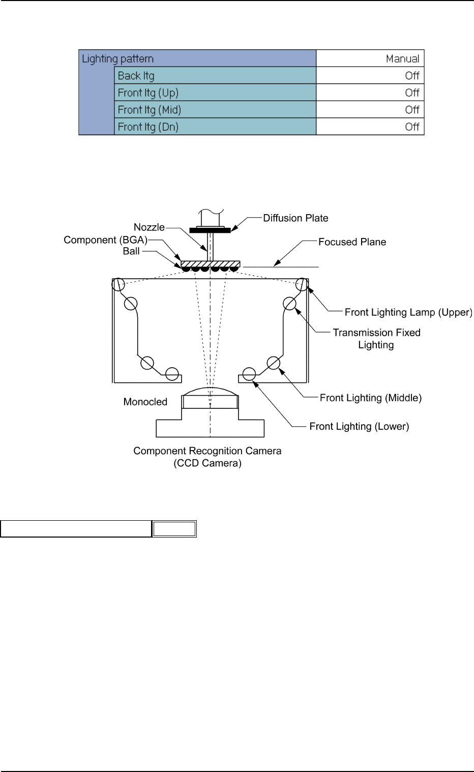
(B02_05) Lighting Pattern
Set a lighting pattern to be used for component recognition.
Applicable Components : Applicable for all subjected components
(1) Ltg Pattern Designation
Select one of the following options to designate a lighting pattern.
Auto : The lighting patterns are automatically set for all lighting
units.
Manual : The lighting patterns can be set individually for each light-
ing unit.
0111-002 2-90
Tg0502-PM-CL
B02 Recognition Data (B02_05)
Fig. B194
Auto
Ltg pattern designation
Fig. B192 Edit Window (Example) for Cylindrical Components
Fig. B193