OM-1076-001.pdf - 第133页
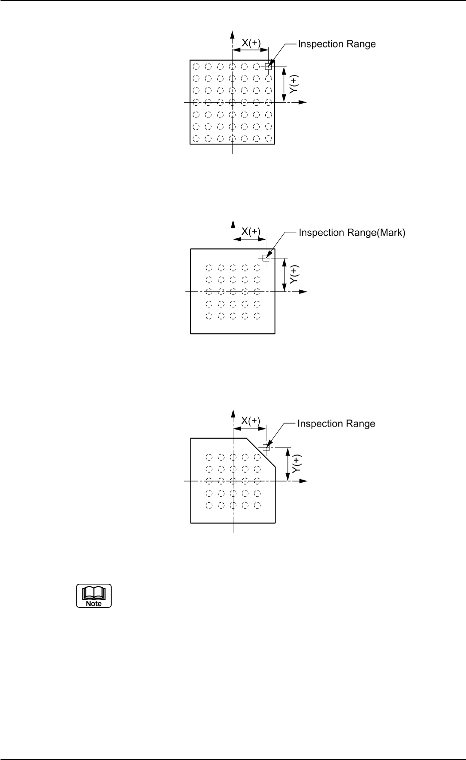
(3) Polarity position X[mm] , Y[mm] Set the distance between the center of the mold and the center of the inspection range. Unit : mm Data Input Range X: -99.99 to +99.99 Y : -99.99 to +99.99 Fig. B219 When this data is …
0206-001 2-101 Tg0502-PM-CL
Example: Regarding the missing ball as a polarity
Top View of Component
Fig. B215
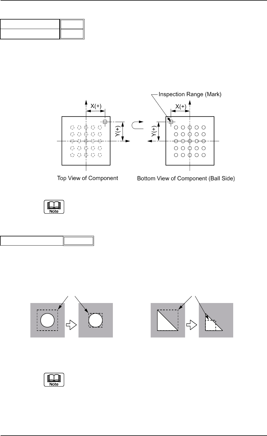
Example: Regarding the mark on the mold as a polarity
Top View of Component
Fig. B216
Example: Regarding the cutout of the mold as a polarity
Top View of Component
Fig. B217
(a) When the cutout on the mold is regarded as a polarity, it should lie
within the back lighting range. Therefore, the subjected mold sizes
are 18 × 18 mm or less.
(b) When the cutout on the mold is regarded as a polarity, use the follow-
ing settings.
Recognition Data Set : Manual
Ltg Pattern Designation: Manual
Back Ltg : - 80 % or - 60 %
Front Ltg (Up) : Std
Front Ltg (Mid) : Off
Front Ltg (Dn) : Off
B02 Recognition Data (B02_16)
(3) Polarity position X[mm] , Y[mm]
Set the distance between the center of the mold and the center of the
inspection range.
Unit : mm
Data Input Range
X: -99.99 to +99.99
Y: -99.99 to +99.99
Fig. B219
When this data is set, set "Enable (Discard)" or "Enable (Placement)" in
the "Polarity detn" text box.
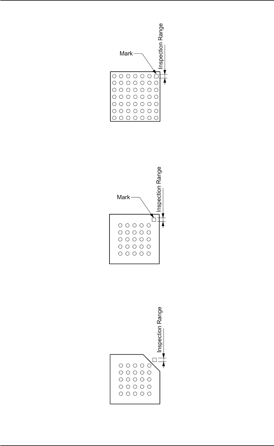
(4) Inspection range [mm]
Set the range to be inspected in the data box.
Unit: mm
Data Input Range : 0.1 to 9.9
Fig. B221
(a) Set the inspection range to select clear brightness or darkness, which
can raise (lower) the determined value and facilitate the determina-
tion.
(b) When this data is set, set "Enable (Discard)" or "Enable (Placement)"
in the "Polarity detn" text box.
0206-001 2-102
Tg0502-PM-CL
PossibleImpossible
PossibleImpossible
Inspection Ranges
Inspection Ranges
Determined Value: 50 Determined Value: 100 Determined Value: 50 Determined Value: 100
Fig. B218
Polarity position X[mm]
Polarity position Y[mm]
+0.00
+0.00
Fig. B220
Inspection range [mm]
0.1
B02 Recognition Data (B02_16)
0206-001 2-103 Tg0502-PM-CL
Example: Regarding the missing ball as a polarity
Top View of Component
Fig. B222
Example: Regarding the mark on the mold as a polarity
Top View of Component
Fig. B223
Example: Regarding the cutout of the mold as a polarity
Top View of Component
Fig. B224
B02 Recognition Data (B02_16)