OM-1076-001.pdf - 第39页
A02 Control Data (A02_02) 0206-001 2-20-1 Tg0502-PM-CL (A02_02) Selected Nozzle #2 Set the nozzle to be used when the nozzle selected in the "Selected Nozzle #1" data box can not be used. Refer to "Selecte…
(17) Cmpnt Detection (Sensor)
Set whether to judge the pick-up quality with the vacuum sensor.
"DISABLE" or "ENABLE" can be selected.
When the nozzle selected in "Selected NOZZLE" meets one of the re-
quirements described in the table below, "DISABLE" is selected auto-
matically.
Table B11
(18) Air blow
From the following items, select whether or not to air blow when the
component is placed.
Enable Disable
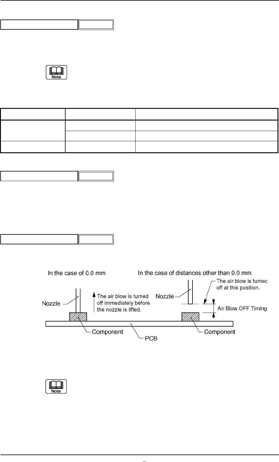
(19) Air blow off timing [mm]
Set the position at which the air blow is turned off.
This function is used when the nozzle error occurs where component
is brought back.
Unit: mm
Data Input Range: 0.0 to 9.9
A02 Control Data (A02_01)
0206-003 2-20 Tg0502-PM-CL
Fig.B30
Cmpnt detection (Sensor)
Disable
Fig.B30-1
Air blow
Enable
Fig.B30-2
Air blow off timing [mm]
0.0
Fig. B30-3
Item Condition Remarks
Nozzle ID EC** Mechanical Chuck Nozzle
EE** Mechanical Chuck Nozzle
Area of Pick-Up Hole Less then 0.7854mm
2
Total Area of Pick-Up Hole
A02 Control Data (A02_02)
0206-001 2-20-1 Tg0502-PM-CL
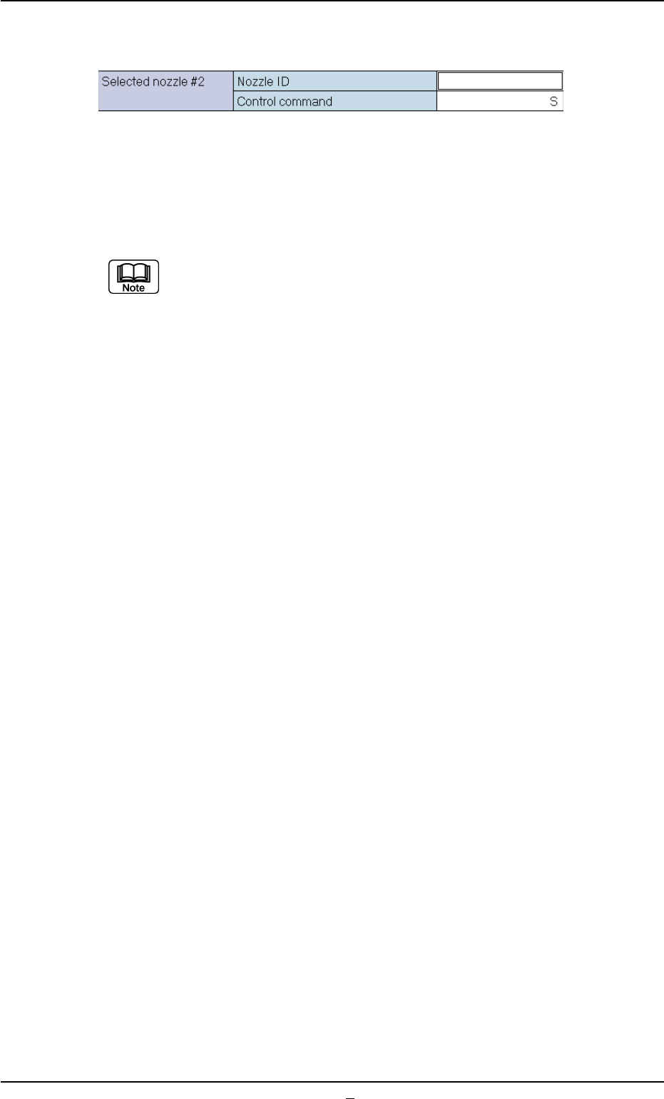
(A02_02) Selected Nozzle #2
Set the nozzle to be used when the nozzle selected in the "Selected
Nozzle #1" data box can not be used.
Refer to "Selected Nozzle #1" for the descriptions for each data.
Nozzles are distinguished according to the difference in end size, shape,
length, etc., and managed using nozzle ID.s.
Fig. B31
A02 Control Data (A02_03)
0107-001 2-21 Tg0502-PM-CL
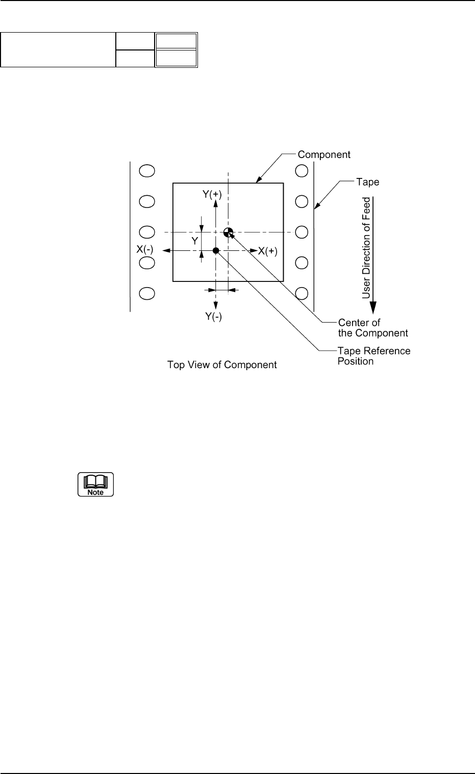
(A02_03) Cmpnt Pos Correction X [mm], Y [mm]
Set the center (coordinate) of a component based on the tape refer-
ence position.
Whether the value with "+" sign or "−" sign should be entered will be
determined according to the following coordinate.
Unit: mm
Data Input Range: −99.9 to +99.9
(a) The reference positions for component pick-up are specified for each
individual feeder No. However, a reference position may deviate from
the center of a component packaged in the tape. In this case, it is
necessary to enter parameters to correct the deviation.
(b) Actual operation range may be regulated (differ from the set values)
due to the control of the machine.
X[mm]
Y[mm]
+0.0
+0.0
Fig.B32
Cmpnt pos correction
Fig. B33