2500_Users_Manual-.pdf - 第136页
Operation Calibrating Labels in the Thermal Printer The label optic must be calibrated to detect and synchronize with the labels after you have finished either one of the following operations: • Installing a new roll of …
2303-1
LABEL DRIVE ROLLER (hidden)
LABEL PINCH ROLLER
LABEL ADVANCE KNOB
LABEL ALIGNMENT ROLLER
LABEL DETECTION OPTIC
LABEL ROLL
(cover removed)
APPLICATION PLATE (raised)
PLATEN
PRINT HEAD
(retracted position)
LABEL ADC OPTIC
PLATEN PINCH ROLLER
Operation
10.
Make
certain
that
the
label
liner
is
flat
against
the
underside
of
the
platen.
11.
Feed
the
liner
back
over
the
top
of
the
platen
and
through
the
gap
between
the
platen
and
the
track.
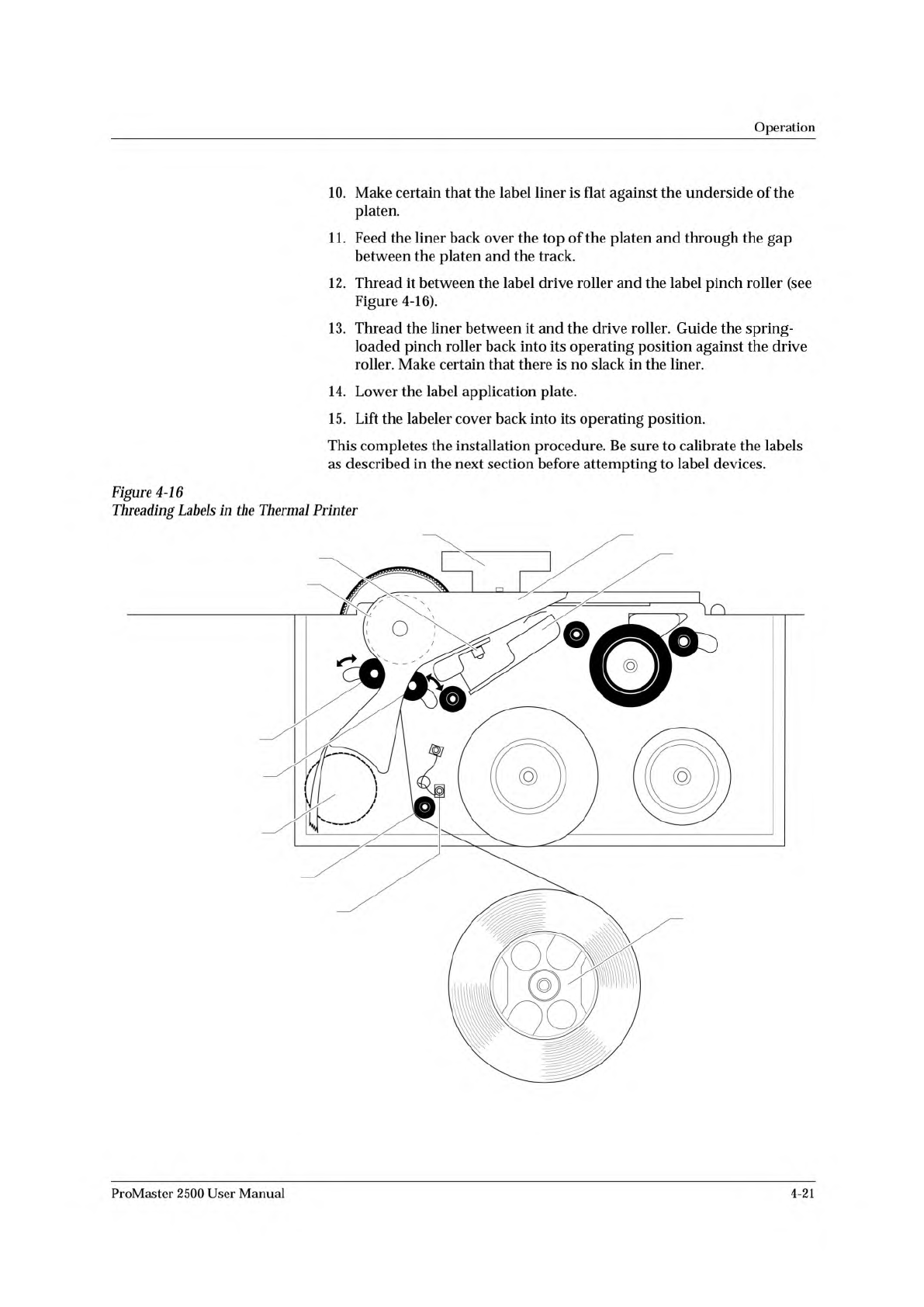
12.
Thread
it
between
the
label
drive
roller
and
the
label
pinch
roller
(see
Figure
4-16).
13.
Thread
the
liner
between
it
and
the
drive
roller.
Guide
the
spring-
loaded
pinch
roller
back
into
its
operating
position
against
the
drive
roller.
Make
certain
that
there
is
no
slack
in
the
liner.
14.
Lower
the
label
application
plate.
15.
Lift
the
labeler
cover
back
into
its
operating
position.
This
completes
the
installation
procedure.
Be
sure
to
calibrate
the
labels
as
described
in
the
next
section
before
attempting
to
label
devices.
Figure
4-16
Threading
Labels
加
the
Thermal
Printer
ProMaster
2500
User
Manual
4-21
Operation
Calibrating
Labels
in
the
Thermal
Printer
The
label
optic
must
be
calibrated
to
detect
and
synchronize
with
the
labels
after
you
have
finished
either
one
of
the
following
operations:
•
Installing
a
new
roll
of
labels
•
Changing
the
ribbon
•
Adjusting
the
ADC
reference
value
•
Manually
moving
the
labels
Perform
the
following
steps
to
calibrate
the
labels.
1.
Put
your
finger
near
the
label
application
point
(the
right
edge
of
the
application
plate).
2.
Press
CAL
on
the
front
panel
of
the
2500.
3.
Use
your
finger
to
catch
the
three
or
four
labels
ejected
while
the
labels
are
being
calibrated.
Installing
Devices
in
the
Input
Track
The
orientation
of
devices
in
the
input
track
is
critical.
The
2500
uses
the
location
of
pin
1
(as
specified
in
the
Task
you
are
running)
to
determine
how
to
rotate
the
beam
so
that
it
correctly
inserts
the
device
in
the
programming
module's
block.
Because
the
way
you
insert
devices
in
the
input
track
is
already
defined
as
part
of
the
Task,
you
must
know
your
company's
standards
and
be
careful
to
insert
each
tube
of
devices
to
match
that
standard.
In
most
cases,
the
default
orientation
defined
by
TaskLink
is
used.
At
the
start
of
a
Task,
TaskLink
displays
a
drawing
with
the
position
that
the
Task
has
defined
for
pin
1
(see
Figure
4-21).
Install
devices
upside-down
so
that
their
leads
point
toward
the
ceiling
(see
Figure
4-17).
The
default
positions
for
pin
1
are:
•
DIP
and
SOIC
devices:
Pin
1
is
to
the
right,
closest
to
the
input
tube.
•
32-pin
PLCC
devices:
Pin
1
is
to
the
right,
closest
to
the
input
tube.
•
Square
PLCC
devices:
Pin
1
is
pointing
to
the
back
of
the
2500.
CAUTION:
Insert
input
tubes
with
the
device
leads
pointing
up
toward
the
ceiling.
Insert
square
PLCC
devices
with
pin
1
oriented
toward
the
back
of
the
2500,
away
from
you.
Insert
rectangular
PLCC
(32-pin),
DIP
and
SOIC
devices
so
that
pin
1
is
oriented
to
the
right.
Failure
to
insert
devices
so
they
match
the
Task
configuration
may
damage
both
the
device
and
the
programming
module.
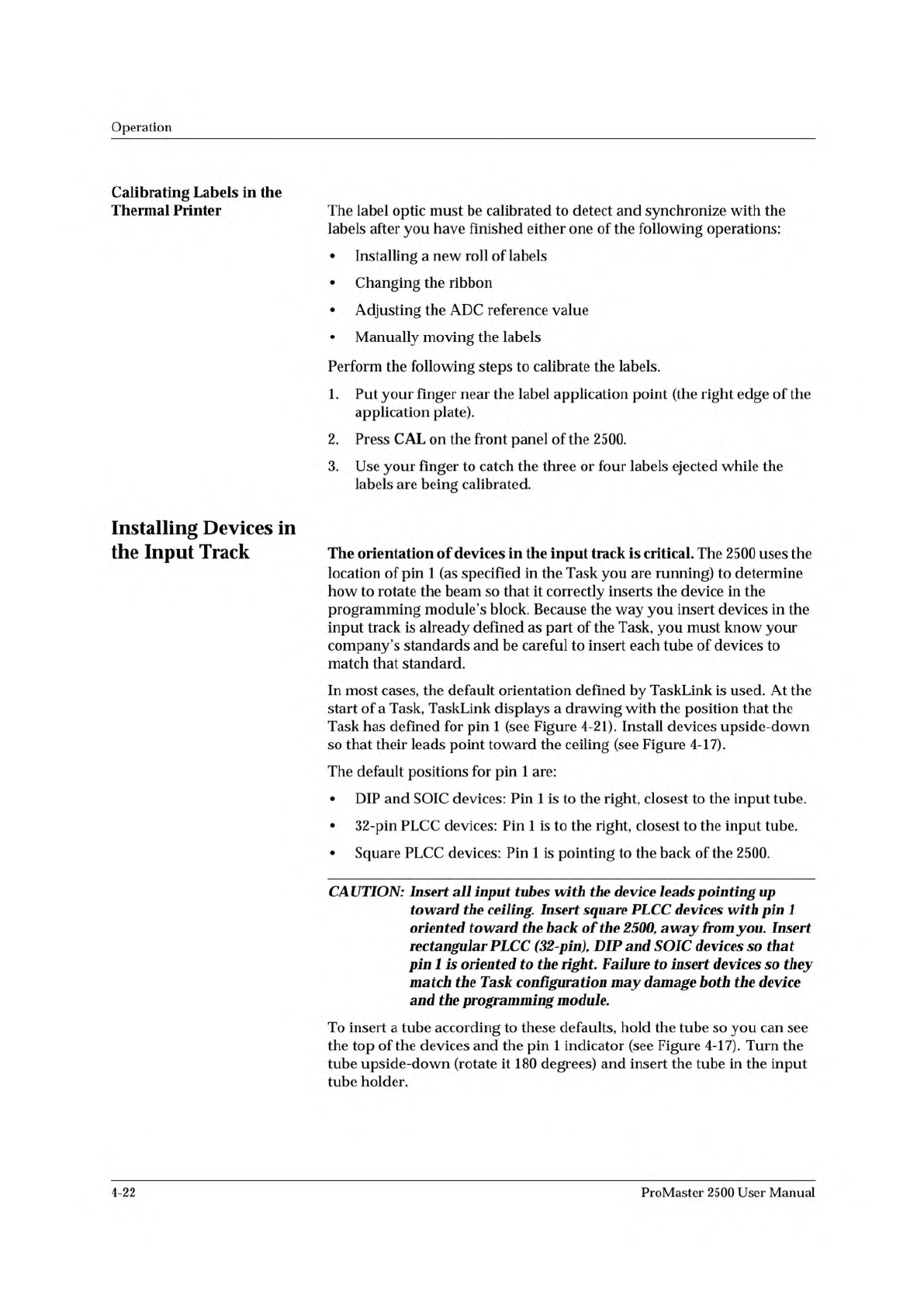
To
insert
a
tube
according
to
these
defaults,
hold
the
tube
so
you
can
see
the
top
of
the
devices
and
the
pin
1
indicator
(see
Figure
4-17).
Turn
the
tube
upside-down
(rotate
it
180
degrees)
and
insert
the
tube
in
the
input
tube
holder.
4-22
ProMaster
2500
User
Manual
1854-3
NOTCHED
CORNER
INPUT TUBE
HOLDER
INPUT TUBE
HOLDER
TUBE INSERTED
WITH DEVICE
CONTACTS
FACING UP
TUBE INSERTED
WITH DEVICE
CONTACTS
FACING UP
SQUARE
PLCC
DEVICES
DIP/SOIC
DEVICES
PIN 1
PIN 1
Figure
4-17
Installing
Devices
in
the
Tu
加
Holder
Operation
Running
a
Task
Start
TaskLink
at
the
DOS
prompt
in
the
directory
where
TaskLink
is
installed.
Type:
tl
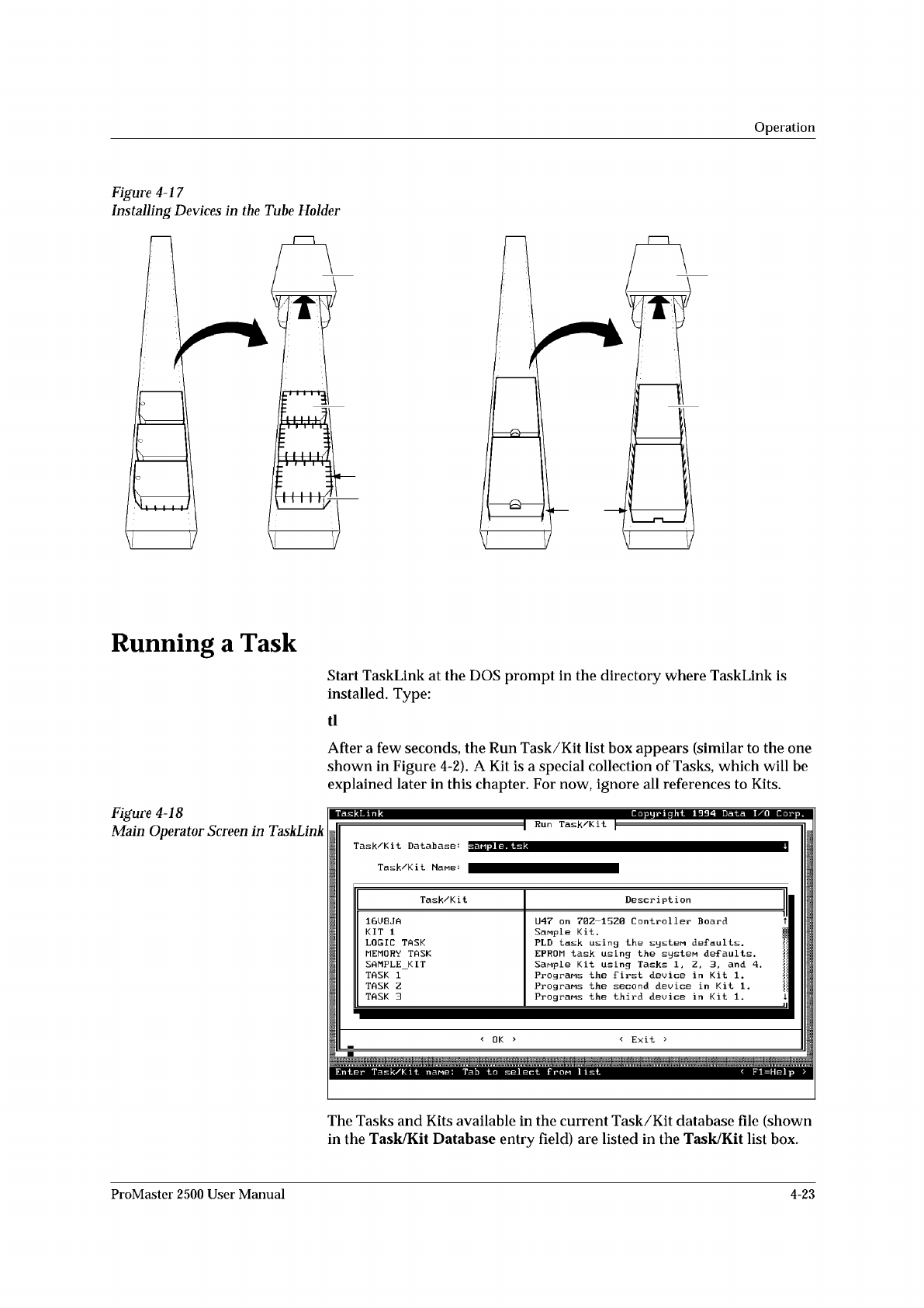
After
a
few
seconds,
the
Run
Task/Kit
list
box
appears
(similar
to
the
one
shown
in
Figure
4-2).
A
Kit
is
a
special
collection
of
Tasks,
which
will
be
explained
later
in
this
chapter.
For
now,
ignore
all
references
to
Kits.
Figure
4-18
Main
Operator
Screen
in
TaskLink
The
Tasks
and
Kits
available
in
the
current
Task/Kit
database
file
(shown
in
the
Task/Kit
Database
entry
field)
are
listed
in
the
Task/Kit
list
box.
ProMaster
2500
User
Manual
4-23