2500_Users_Manual-.pdf - 第148页
↑ ↓ In Progress Waiting For Devices Operation 3. If the device was too close to the front of the programming module, press on the 2500's keyboard once or twice. If the device was too close to the back of the program…
PROGRAM/TEST ONLY
USE ARROW KEYS TO ALIGN BEAM WITH
DEVICE CENTER. PRESS [D] TO LOWER BEAM.
PRESS START TO CONTINUE.
1945-2
Operation
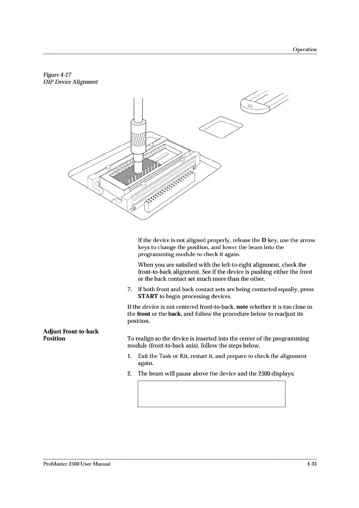
Figure
4-27
DIP
Device
Alignment
Adjust
Front-to-back
Position
If
the
device
is
not
aligned
properly,
release
the
D
key,
use
the
arrow
keys
to
change
the
position,
and
lower
the
beam
into
the
programming
module
to
check
it
again.
When
you
are
satisfied
with
the
left-to-right
alignment,
check
the
front-to-back
alignment.
See
if
the
device
is
pushing
either
the
front
or
the
back
contact
set
much
more
than
the
other.
7.
If
both
front
and
back
contact
sets
are
being
contacted
equally,
press
START
to
begin
processing
devices.
If
the
device
is
not
centered
front-to-back,
note
whether
it
is
too
close
to
the
front
or
the
back,
and
follow
the
procedure
below
to
readjust
its
position.
To
realign
so
the
device
is
inserted
into
the
center
of
the
programming
module
(front-to-back
axis),
follow
the
steps
below.
1.
Exit
the
Task
or
Kit,
restart
it,
and
prepare
to
check
the
alignment
again.
2.
The
beam
will
pause
above
the
device
and
the
2500
displays:
ProMaster
2500
User
Manual
4-33
↑
↓
In
Progress
Waiting For Devices
Operation
3.
If
the
device
was
too
close
to
the
front
of
the
programming
module,
press
on
the
2500's
keyboard
once
or
twice.
If
the
device
was
too
close
to
the
back
of
the
programming
module,
press
once
or
twice.
4.
Press
START.
The
beam
moves
the
device
over
the
programming
module
and
stops.
5.
Press
and
hold
D
on
the
2500
keyboard
to
make
certain
that
the
device
is
equidistant
between
the
front
and
back
contact
sets.
Repeat
steps
1
through
5
until
the
device
moves
into
the
center
of
the
programming
module
and
is
not
closer
to
one
side
of
the
contacts
than
the
other.
6.
When
the
alignment
is
correct,
press
START
to
continue
running
the
Task.
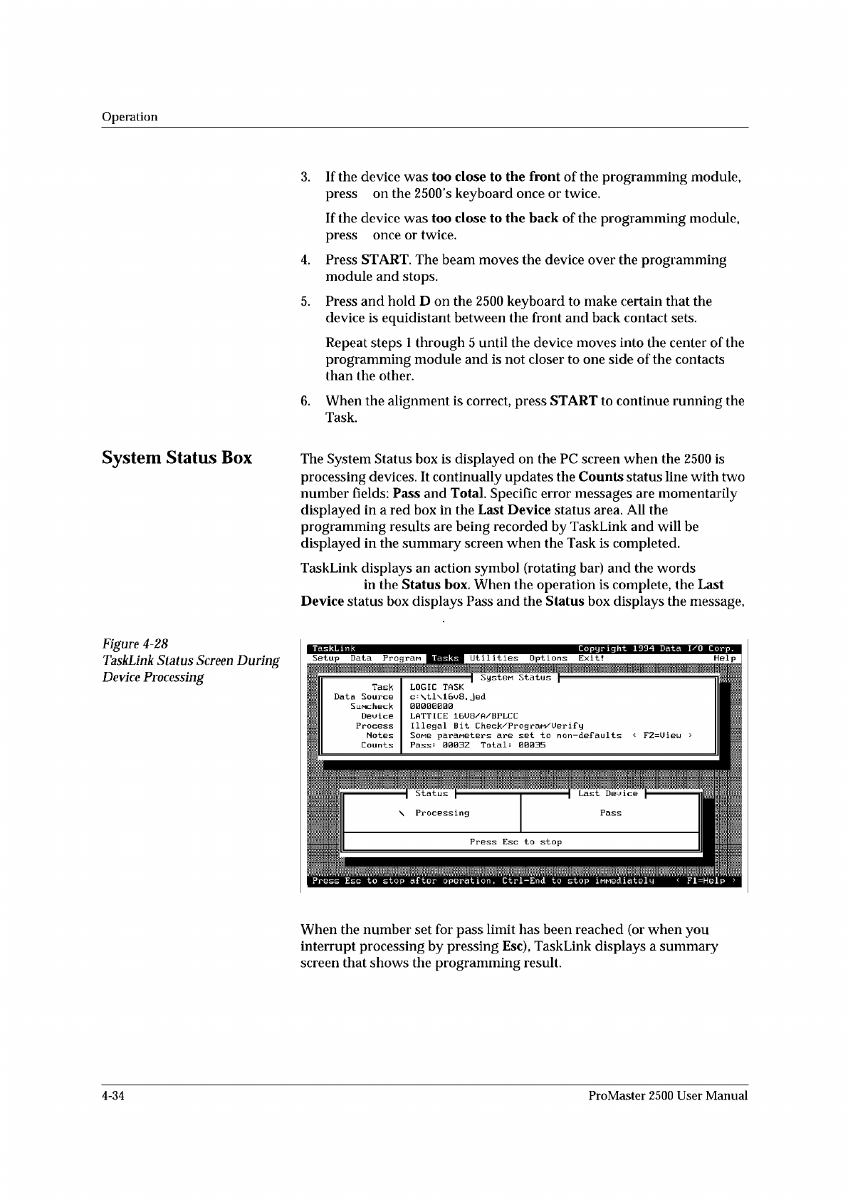
System
Status
Box
The
System
Status
box
is
displayed
on
the
PC
screen
when
the
2500
is
processing
devices.
It
continually
updates
the
Counts
status
line
with
two
number
fields:
Pass
and
Total.
Specific
error
messages
are
momentarily
displayed
in
a
red
box
in
the
Last
Device
status
area.
All
the
programming
results
are
being
recorded
by
TaskLink
and
will
be
displayed
in
the
summary
screen
when
the
Task
is
completed.
TaskLink
displays
an
action
symbol
(rotating
bar)
and
the
words
in
the
Status
box.
When
the
operation
is
complete,
the
Last
Device
status
box
displays
Pass
and
the
Status
box
displays
the
message,
Figure
4-28
TaskLink
Status
Screen
During
Device
Processing
Help
I
Status
、
Processing
TaskLink
Copyright
1994
Data
I/O
Corp.
Tasks
Util
it
les
Options
Exit!
Setup
Data
Progran
Task
Data
Source
SiiMcheck
Dau
i
ca
Process
Notes
Counts
SysteM
Status
LOGIC
TASK
c=
\tl\16u8.
jed
I.ATTI[:K
Illegal
Bit
Check/PrograM/Uerif
y
Somg
paraneters
are
set
to
non-defaults
<
FZ=Uiau
>
Total:
00035
Pass
:
0003Z
Press
Esc
to
stop
after
operation
,
Ctrl-End
to
stop
iMMediately
<
Fl=Help
>
When
the
number
set
for
pass
limit
has
been
reached
(or
when
you
interrupt
processing
by
pressing
Esc),
TaskLink
displays
a
summary
screen
that
shows
the
programming
result.
4-34
ProMaster
2500
User
Manual
Preventive
Maintenance
High
Air
Pressure
Beam
Programming
Module
Clamp
Assembly
High
pressure
air
is
routed
from
the
high
pressure
regulator
to
a
Y
connection
and
is
divided
into
beam
high
pressure
and
programming
module
clamp
assembly
air
pressure.
The
beam
high
pressure
air
is
routed
to
the
beam
by
a
black
air
line
that
passes
through
the
beam
and
into
a
straight-in
air
fitting
on
the
back
right
side
of
the
beam.
This
air
passes
two
milled-in
air
caps
(cavities),
which
dampen
air
spikes,
and
goes
to
solenoids
6
and
7,
mounted
to
the
left
center
of
the
beam.
Creating
the
Beam
Vacuum
The
beam
vacuum
required
to
hold
a
device
on
the
chuck
is
created
when
solenoid
7
(vacuum)
is
activated.
The
high
pressure
air
passes
through
the
beam
passes
through
the
top
hole
of
the
vacuum
venturi,
and
escapes
through
holes
in
the
bottom
of
the
beam.
As
this
rush
of
air
passes
the
venturi,
it
creates
a
vacuum
at
the
chuck
tip.
During
the
optics
test,
the
vacuum
value
should
fluctuate
between
about
26
(when
no
device
is
on
the
chuck)
and
172,
with
a
value
of
140
minimum
for
proper
vacuum.
The
vacuum
is
sensed
by
the
vacuum
sensor
(mounted
at
the
left
front
of
the
beam).
When
a
predefined
vacuum
level
is
detected
by
a
device
blocking
the
chuck
tip,
the
2500
assumes
that
the
beam
has
picked
up
a
device.
A
malfunction
of
the
vacuum
generator,
the
vacuum
sensor,
or
the
microswitch
can
cause
an
error
message
on
the
2500's
display
stating
that
the
beam
has
dropped
the
device
or
is
unable
to
pick
up
the
device.
Inserting
a
Device
into
the
Module
Low
pressure
air
lowers
the
beam
to
the
programming
module
contacts.
Additional
force
is
required
to
insert
the
device
into
the
programming
module.
Insertion
begins
when
the
high
pressure
air
present
at
hole
4
is
switched
to
hole
5
by
beam
solenoid
6
(high
pressure).
This
high
pressure
passes
to
hole
21,
pushing
the
ball
bearing
down
and
sealing
off
the
low
pressure
of
hole
19.
This
allows
high
pressure
to
pass
to
hole
20
and
enter
the
bottom
of
the
cylinder
at
hole
18.
Air
pushing
against
the
fixed
piston
pushes
the
beam
down
to
establish
the
required
continuity
between
the
devices
leads
and
the
module's
contacts.
Programming
module
clamp
assembly
air
is
switched
by
solenoid
8
to
either
open
the
clamps
(to
remove
a
module)
or
close
the
clamps
(to
hold
a
module
in
place).
Red
air
lines
carry
air
to
close
the
clamps;
blue
air
lines
carry
air
to
open
the
clamps.
In-line
valves
on
these
lines
control
the
amount
of
air
entering
the
air
cylinders
and
allow
ac^ustment
so
each
side
of
the
clamp
opens
and
closes
at
the
same
rate.
The
in-line
valves
for
the
red
lines
are
in
the
middle
of
the
air
lines,
while
the
valves
for
the
blue
lines
are
at
the
base
of
each
air
cylinder.
5-12
ProMaster
2500
User
Manual