2500_Users_Manual-.pdf - 第208页
↵ ↵ ↵ ???? Programmi ng hardware has not passed self test Preventive Maintenance 4. Press Fl. If you are prompted to select a new terminal type, press to accept the default. 5. Select M (More Commands) and S (Self-test) …
178
3940
PIN 28 (8MHz)
PIN 24 (+15V)
PIN 1 (Ground)PIN 78 (+10V)
PIN 72 (Plugged)
2143-1
Preventive
Maintenance
4.
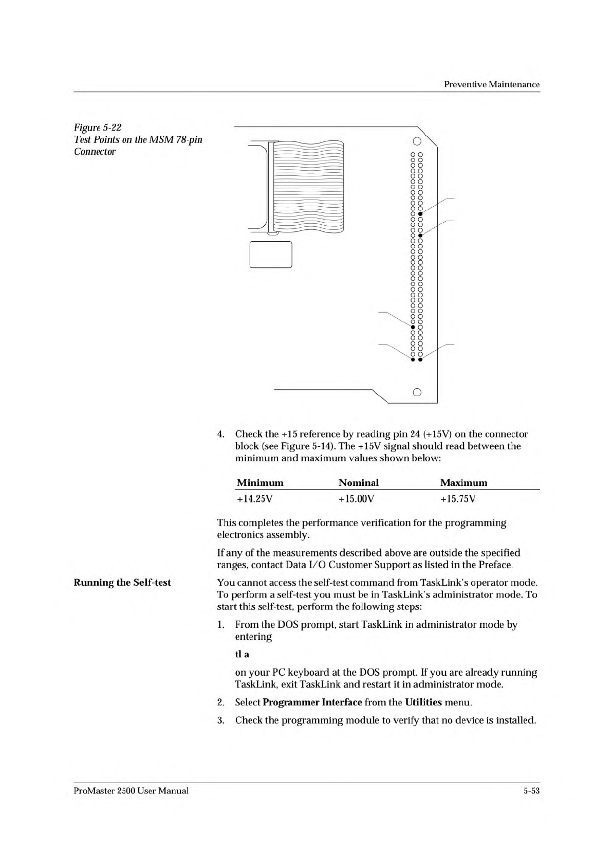
Check
the
+15
reference
by
reading
pin
24
(+15V)
on
the
connector
block
(see
Figure
5-14).
The
+15V
signal
should
read
between
the
minimum
and
maximum
values
shown
below:
Minimum
Nominal
Maximum
+14.25V
+15.00V
+15.75V
This
completes
the
performance
verification
for
the
programming
electronics
assembly.
If
any
of
the
measurements
described
above
are
outside
the
specified
ranges,
contact
Data
I/O
Customer
Support
as
listed
in
the
Preface.
You
cannot
access
the
self-test
command
from
TaskLink's
operator
mode.
To
perform
a
self-test
you
must
be
in
TaskLink's
administrator
mode.
To
start
this
self-test,
perform
the
following
steps:
1.
From
the
DOS
prompt,
start
TaskLink
in
administrator
mode
by
entering
tl
a
on
your
PC
keyboard
at
the
DOS
prompt.
If
you
are
already
running
TaskLink,
exit
TaskLink
and
restart
it
in
administrator
mode.
2.
Select
Programmer
Interface
from
the
Utilities
menu.
3.
Check
the
programming
module
to
verify
that
no
device
is
installed.
Figure
5-22
Test
Points
on
the
MSM
78-p
加
Connector
Running
the
Self-test
ProMaster
2500
User
Manual
5-53
↵
↵
↵
????
Programming hardware has not passed
self test
Preventive
Maintenance
4.
Press
Fl.
If
you
are
prompted
to
select
a
new
terminal
type,
press
to
accept
the
default.
5.
Select
M
(More
Commands)
and
S
(Self-test)
to
get
to
the
Self-test
screen.
6.
Select
the
One
Pass
mode
to
perform
all
the
displayed
tests
once.
7.
Move
the
cursor
to
the
Test
Mode
field
and
press
SPACE.
You
may
stop
the
test
by
pressing
CTRL
+
Z.
There
may
be
a
delay
before
the
system
responds
to
the
Ctrl-Z
if
you
are
testing
system
RAM.
CAUTION:
Executing
the
System
RAM
test
or
the
User
RAM
test
erases
data
in
RAM.
8.
To
test
all
hardware,
move
the
cursor
to
the
Perform
All
Tests
prompt
and
press
.
To
test
a
particular
item,
move
the
cursor
to
the
desired
test
and
press
.
One
of
the
following
four
characters
will
appear
next
to
each
test
to
indicate
the
status
of
that
test:
?
Untested
Pass
Fail
_
Not
Installed
When
testing
begins,
a
question
mark
(?)
appears
next
to
the
untested
areas.
As
each
test
completes,
either
PASS
or
FAIL
appears
next
to
the
test
name
to
show
the
results
of
that
test.
The
may
be
displayed
on
some
tests
if
the
programming
electronics
has
failed
an
earlier
test.
In
this
case
the
means
that
this
item
was
not
tested
and
will
not
run
until
the
earlier
failure
has
been
corrected.
Note:
When
you
abort
a
test,
a
status
of
is
displayed,
and
if
you
try
to
run
TaskLink,
the
message
is
displayed.
A
hyphen
(-)
indicates
that
an
item
is
not
installed
on
your
ProMaster
2500
system.
While
a
test
is
being
performed,
a
rotating
action
symbol
and
a
status
message
are
displayed
in
the
upper,
left
corner
of
the
TaskLink
screen.
Tests
are
performed
in
the
following
order:
1.
Calibration
of
the
supplies
(on
the
controller/
waveform
board)
2.
Pin
control
unit
test
(on
the
controller/waveform
board)
3.
EPROM
(on
the
controller/waveform
board)
4.
Serial
ports
(on
the
controller/waveform
board)
5.
System
RAM
(on
the
controller/
waveform
board)
6.
User
RAM
(on
the
controller/waveform
board)
7.
Disk
drive
8.
Programming
module/relays
(on
the
pin
driver
boards)
5-54
ProMaster
2500
User
Manual
ELECTRONIC ID ERROR
ERROR CLEARED, PRESS
START
DEVICE WAS DROPPED, PRESS START
HARDWARE DID NOT PASS
SELF-TEST
HOOD UP
ILLEGAL BIT
LABEL JAM, PRESS START
LABELS NOT CALIBRATED,
PRESS START
NON-BLANK
PROGRAM FAIL
Troubleshooting
The
internal
electronic
ID
of
the
device
that
is
being
programmed
did
not
match
the
ID
that
the
2500
expected.
Check
that
the
correct
devices
are
being
used
for
this
Task.
This
message
is
displayed
when
the
error
condition
was
corrected.
Error
occurs
when
a
device-related
operation
has
been
attempted
for
the
first
time
after
turning
the
2500
on.
A
critical
assembly
in
the
programming
electronics
has
failed.
Run
the
programming
electronics
self-test
as
described
on
page
5-50.
The
hood
was
up
when
you
started
a
handler
operation.
Lower
the
hood
and
press
START.
A
device
has
a
bit
programmed
and
the
2500's
RAM
indicates
that
it
should
be
blank
(unprogrammed)
.
If
the
devices
are
not
erasable,
the
device
cannot
be
programmed.
If
the
devices
are
erasable,
try
erasing
and
reprogramming.
The
labels
did
not
move
properly.
Make
sure
the
label
advance
rollers
are
clean,
the
pinch
rollers
are
engaged,
and
the
label
detection
optics
are
functioning
properly.
Make
sure
the
label
motor
is
operating
and
that
the
drive
belt
is
properly
installed.
Check
the
pulley
for
loose
set
screws.
Make
sure
that
the
label
reel
has
labels.
The
labels
did
not
calibrate
properly.
Make
sure
the
label
advance
rollers
are
clean,
the
pinch
rollers
are
fully
engaged,
and
the
ADC
optics
are
functioning
properly.
Check
the
ADC
optic
value
in
the
Optics
test.
Make
sure
that
the
label
advance
motor
is
operating.
Make
sure
that
the
label
reel
has
labels.
Make
sure
that
the
label
stock
is
not
sticking
to
the
liner.
The
2500
has
detected
bits
in
the
device
that
are
not
in
their
unprogrammed
message
state
and
are
not
illegal
bits.
The
devices
are
probably
programmable,
but
will
not
be
programmed
and
will
be
sent
to
the
fail
output
tube
when
Blank
Check
has
been
selected
as
a
Task
process.
The
2500
will
try
to
program
a
non-blank
device
if
Blank
Check
is
not
selected
in
the
Task's
process.
The
2500
has
applied
the
maximum
number
of
programming
pulses
according
to
the
device
manufacturer's
specifications
and
the
device
is
not
programmed.
The
device
should
be
discarded.
ProMaster
2500
User
Manual
6-3