2500_Users_Manual-.pdf - 第186页
OPTIC TEST - ADC = 200 - VAC = XX 1110000000111 1101111111100 ENC = 13107 | | | | | U15 REV X.XX 5 10 15 20 25 U43 REV X.XX Preventive Maintenance Optic Test The optic test verifies that the optics and microswitches are …
2516-1
Preventive
Maintenance
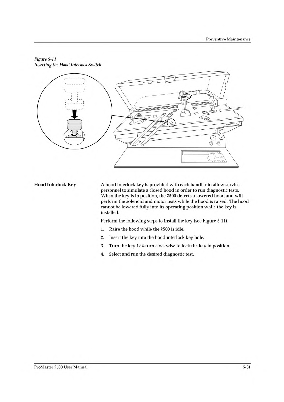
Figure
5-11
Inserting
the
Hood
Interlock
Switch
Hood
Interlock
Key
A
hood
interlock
key
is
provided
with
each
handler
to
allow
service
personnel
to
simulate
a
closed
hood
in
order
to
run
diagnostic
tests.
When
the
key
is
in
position,
the
2500
detects
a
lowered
hood
and
will
perform
the
solenoid
and
motor
tests
while
the
hood
is
raised.
The
hood
cannot
be
lowered
fully
into
its
operating
position
while
the
key
is
installed.
Perform
the
following
steps
to
install
the
key
(see
Figure
5-11).
1.
Raise
the
hood
while
the
2500
is
idle.
2.
Insert
the
key
into
the
hood
interlock
key
hole.
3.
Turn
the
key
1/
4-turn
clockwise
to
lock
the
key
in
position.
4.
Select
and
run
the
desired
diagnostic
test.
ProMaster
2500
User
Manual
5-31
OPTIC TEST - ADC = 200 - VAC = XX
11100000001111101111111100 ENC = 13107
| | | | | U15 REV X.XX
5 10 15 20 25 U43 REV X.XX
Preventive
Maintenance
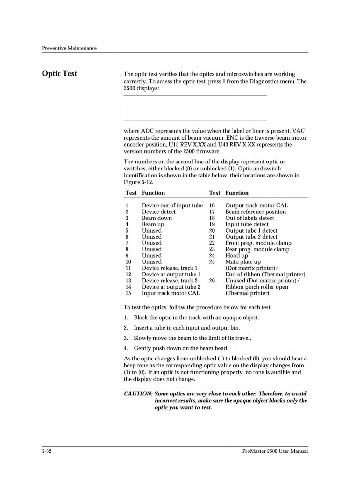
Optic
Test
The
optic
test
verifies
that
the
optics
and
microswitches
are
working
correctly.
To
access
the
optic
test,
press
1
from
the
Diagnostics
menu.
The
2500
displays:
where
ADC
represents
the
value
when
the
label
or
liner
is
present,
VAC
represents
the
amount
of
beam
vacuum,
ENC
is
the
traverse
beam
motor
encoder
position,
U15
REV
X.XX
and
U43
REV
X.XX
represents
the
version
numbers
of
the
2500
firmware.
The
numbers
on
the
second
line
of
the
display
represent
optic
or
switches,
either
blocked
(0)
or
unblocked
Optic
and
switch
identification
is
shown
in
the
table
below;
their
locations
are
shown
in
Figure
5-12.
Test
Function
Test
Function
1
Device
out
of
input
tube
16
Output
track
motor
CAL
2
Device
detect
17
Beam
reference
position
3
Beam
down
18
Out
of
labels
detect
4
Beam
up
19
Input
tube
detect
5
Unused
20
Output
tube
1
detect
6
Unused
21
Output
tube
2
detect
7
Unused
22
Front
prog,
module
clamp
8
Unused
23
Rear
prog,
module
clamp
9
Unused
24
Hood
up
10
Unused
25
Main
plate
up
11
Device
release,
track
1
(Dot
matrix
printer)/
12
Device
at
output
tube
1
End
of
ribbon
(Thermal
printer)
13
Device
release,
track
2
26
Unused
(Dot
matrix
printer)/
14
Device
at
output
tube
2
Ribbon
pinch
roller
open
15
Input
track
motor
CAL
(Thermal
printer)
To
test
the
optics,
follow
the
procedure
below
for
each
test.
1.
Block
the
optic
in
the
track
with
an
opaque
object.
2.
Insert
a
tube
in
each
input
and
output
bin.
3.
Slowly
move
the
beam
to
the
limit
of
its
travel.
4.
Gently
push
down
on
the
beam
head.
As
the
optic
changes
from
unblocked
(1)
to
blocked
(0),
you
should
hear
a
beep
tone
as
the
corresponding
optic
value
on
the
display
changes
from
(1)
to
(0).
If
an
optic
is
not
functioning
properly,
no
tone
is
audible
and
the
display
does
not
change.
CAUTION:
Some
optics
are
very
close
to
each
other.
Therefore,
to
avoid
incorrect
results,
make
sure
the
opaque
object
blocks
only
the
optic
you
want
to
test.
5-32
ProMaster
2500
User
Manual
1939-1
1
15 (Under main plate)
2
17
3
4
13
14
20 (Output tube 1)
21 (Output tube 2)
19
11
12
16 (Under main plate)
22
23
Preventive
Maintenance
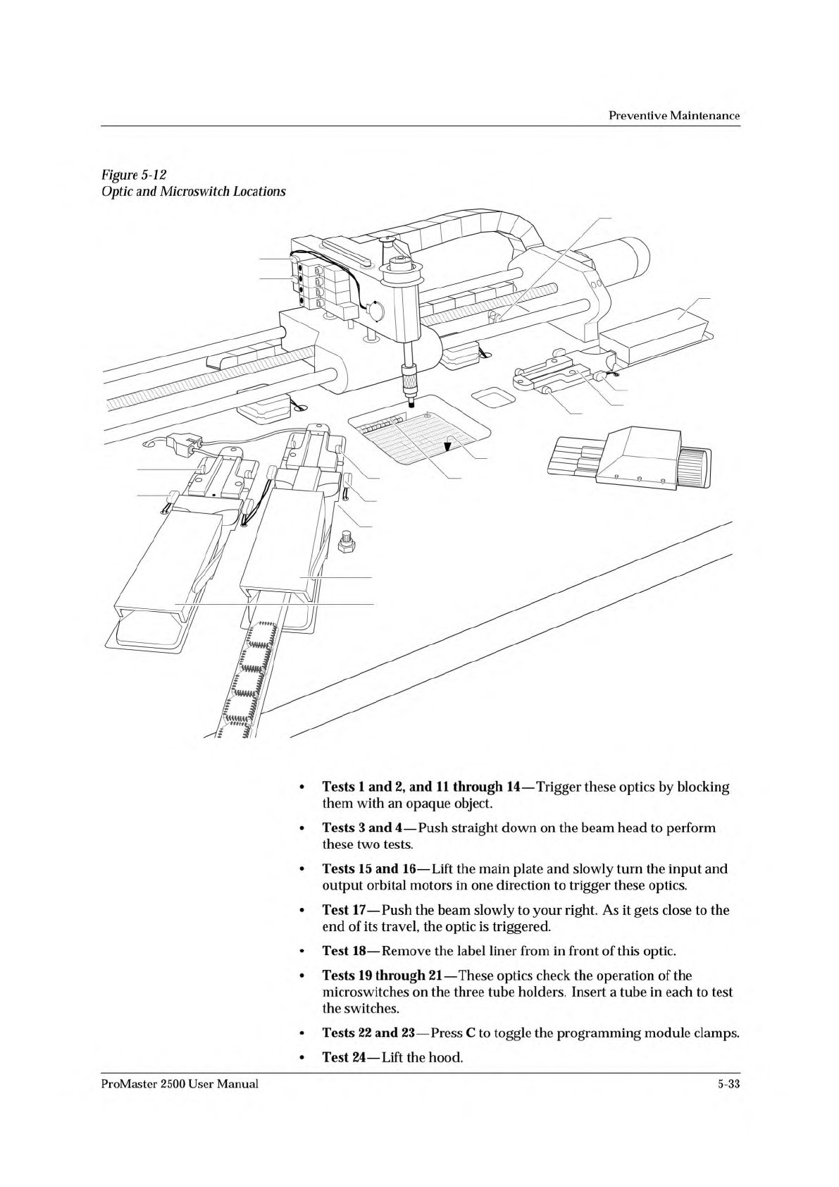
Figure
5-12
Optic
and
Microswitch
Locations
•
Tests
1
and
2,
and
11
through
14
—
Trigger
these
optics
by
blocking
them
with
an
opaque
object.
•
Tests
3
and
4
—
Push
straight
down
on
the
beam
head
to
perform
these
two
tests.
•
Tests
15
and
16
—
Lift
the
main
plate
and
slowly
turn
the
input
and
output
orbital
motors
in
one
direction
to
trigger
these
optics.
•
Test
17
—
Push
the
beam
slowly
to
your
right.
As
it
gets
close
to
the
end
of
its
travel,
the
optic
is
triggered.
•
Test
18
—
Remove
the
label
liner
from
in
front
of
this
optic.
•
Tests
19
through
21
—
These
optics
check
the
operation
of
the
microswitches
on
the
three
tube
holders.
Insert
a
tube
in
each
to
test
the
switches.
•
Tests
22
and
23
—
Press
C
to
toggle
the
programming
module
clamps.
•
Test
24
—
Lift
the
hood.
ProMaster
2500
User
Manual
5-33