2500_Users_Manual-.pdf - 第349页
Translation Formats JEDEC Field Syntax <field> :: = [<delimiter>]<field identifler>{<field character〉}'*' <field identifier>::= 'A' | C | 'D' | F | 'G' |…
ABEL(tm) Version 2.00b JEDEC file for:P20R8
Large Memory Version
Created on: 09-Mar-87 04:45 PM
8-bit barrel shifter
EngineerI Data I/O Corp Redmond WA 10 Jan 1986*
QP24* QF2560*
L0000
1101111111111111111111111111101110111010
1101111111111111111111111011111110111001
1101111111111111111110111111111110110110
1101111111111111101111111111111110110101
1101111111111011111111111111111101111010
1101111110111111111111111111111101111001
1001101111111111111111111111111101110110
1001111111111111111111111111111101110101
1001111111111111111111111111101101110101
1101111111111111111111111111101110111010
1101111111111111111111111011111110111001
1101111111111111111110111111111110110110
1101111111111111101111111111111110110101
1101111111111011111111111111111101111010
1101111110111111111111111111111101111001
1001101111111111111111111111111101110110
1001111111111111111111111111111101110101
1001111111111111111111111111101101110101*
V0001 C1000000000N00HLLLLLLL1N*
V0002 C1000000000N01LHLLLLLL1N*
V0003 C1000000001N00LLHLLLLL1N*
V0004 C1000000001N01LLLHLLLL1N*
V0005 C1000000010N00LLLLHLLL1N*
V0006 C1000000010N01LLLLLHLL1N*
V0007 C1000000011N00LLLLLLHL1N*
V0008 C1000000011N01LLLLLLLH1N*
V0009 C0111111100N00LHHHHHHH1N*
V0010 C0111111100N01HLHHHHHH1N*
V0011 C0111111101N00HHLHHHHH1N*
V0012 C0111111101N01HHHLHHHH1N*
V0013 C0111111110N00HHHHLHHH1N*
V0014 C0111111110N01HHHHHLHH1N*
V0015 C0111111111N00HHHHHHLH1N*
V0016 C0111111111N01HHHHHHHL1N*
V0017 C0000000100N01HLLLLLLL1N*
V0018 C1111111000N01LHHHHHHH1N*
V0019 C0000000000N00HHHHHHHH0N*
V0020 C0000000000N10ZZZZZZZZ1N*
C1B20*
B8C0
Header
(comment area -
everything
preceeding
first * is
ignored)
Number of Pins (24)
and Number of Fuses (2560)
Fuse Address (0000)
Fuse States:
0 = intact
1 = blown
Test Vectors
Fuse Map Checksum
Transmission Checksum
0090-3
Vector
Number
Translation
Formats
JEDEC
Full
Format,
Code
91
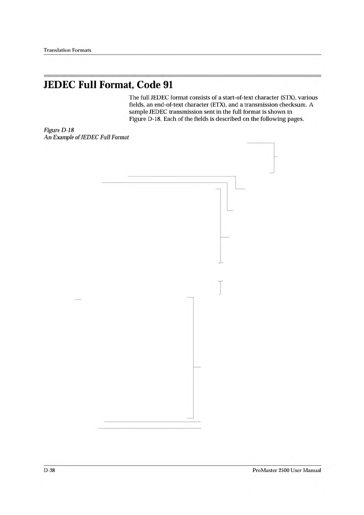
The
full
JEDEC
format
consists
of
a
start-of-text
character
(STX),
various
fields,
an
end-of-text
character
(ETX),
and
a
transmission
checksum.
A
sample
JEDEC
transmission
sent
in
the
full
format
is
shown
in
Figure
D-18.
Each
of
the
fields
is
described
on
the
following
pages.
Figure
D-18
An
Example
of
JEDEC
Full
Format
D-38
ProMaster
2500
User
Manual
Translation
Formats
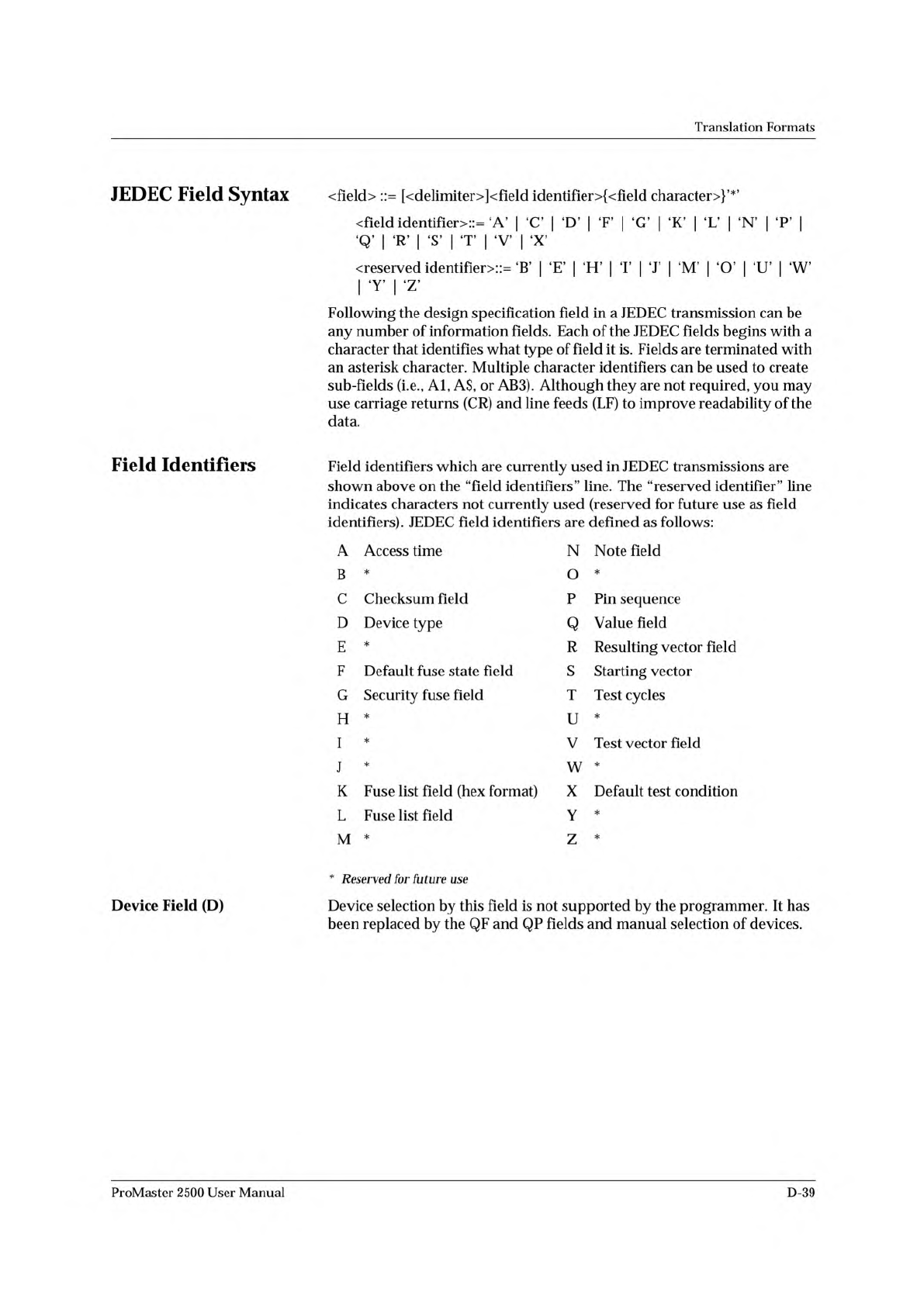
JEDEC
Field
Syntax
<field>
::
=
[<delimiter>]<field
identifler>{<field
character〉}'*'
<field
identifier>::=
'A'
|
C
|
'D'
|
F
|
'G'
|
K
|
'L'
|
'N'
|
P
|
qTrTstttvtx,
〈
reserved
identifier>::=
'B'
|
E
|
'H'
|
T
|
'J'
|
'M'
「
0'
|
'U'
|
'W'
1
,y,
।
Z
Following
the
design
specification
field
in
a
JEDEC
transmission
can
be
any
number
of
information
fields.
Each
of
the
JEDEC
fields
begins
with
a
character
that
identifies
what
type
of
field
it
is.
Fields
are
terminated
with
an
asterisk
character.
Multiple
character
identifiers
can
be
used
to
create
sub-fields
(i.e.,
Al,
A$,
or
AB3).
Although
they
are
not
required,
you
may
use
carriage
returns
(CR)
and
line
feeds
(LF)
to
improve
readability
of
the
data.
Field
Identifiers
Field
identifiers
which
are
currently
used
in
JEDEC
transmissions
are
shown
above
on
the
“field
identifiers
n
line.
The
“reserved
identifier
M
line
indicates
characters
not
currently
used
(reserved
for
future
use
as
field
identifiers).
JEDEC
field
identifiers
are
defined
as
follows:
A
Access
time
N
Note
field
B
*
O
*
C
Checksum
field
P
Pin
sequence
D
Device
type
Q
Value
field
E
*
R
Resulting
vector
field
F
Default
fuse
state
field
S
Starting
vector
G
Security
fuse
field
T
Test
cycles
H
*
U
*
I
*
V
Test
vector
field
J
*
w
*
K
Fuse
list
field
(hex
format)
X
Default
test
condition
L
Fuse
list
field
Y
*
M
*
Z
*
Device
Field
(D)
*
Reserved
for
future
use
Device
selection
by
this
field
is
not
supported
by
the
programmer.
It
has
been
replaced
by
the
QF
and
QP
fields
and
manual
selection
of
devices.
ProMaster
2500
User
Manual
D-39
Translation
Formats
Although
each
data
byte
has
an
address,
most
are
implied.
Data
bytes
are
addressed
sequentially
unless
an
explicit
address
is
included
in
the
data
stream.
This
address
is
preceded
by
a
$
and
an
A,
must
contain
2
to
8
hex
or
3
to
11
octal
characters,
and
must
be
followed
by
a
comma,
except
for
the
ASCII-Hex
(Comma)
format,
which
uses
a
period.
The
programmer
skips
to
the
new
address
to
store
the
next
data
byte;
succeeding
bytes
are
again
stored
sequentially.
Each
format
has
an
end
code,
which
terminates
input
operations.
However,
if
a
new
start
code
follows
within
16
characters
of
an
end
code,
input
will
continue
uninterrupted.
If
no
characters
come
within
2
seconds,
input
operation
is
terminated.
After
receiving
the
final
end
code
following
an
input
operation,
the
programmer
calculates
a
sumcheck
of
all
incoming
data.
Optionally,
a
sumcheck
can
also
be
entered
in
the
input
data
stream.
The
programmer
compares
this
sumcheck
with
its
own
calculated
sumcheck.
If
they
match,
the
programmer
will
display
the
sumcheck;
if
not,
a
sumcheck
error
will
be
displayed.
Note:
The
sumcheck
field
consists
of
either
2-4
hex
or
3-6
octal
characters,
sandwiched
between
the
$
and
comma
characters.
The
sumcheck
immediately
follows
end
code.
The
sumcheck
is
optional
in
the
input
mode
but
is
always
included
in
the
output
mode.
The
most
significant
digit
of
the
sumcheck
may
be
0
or
1
when
expressing
1
6
bits
as
6
octal
characters.
The
programmer
divides
the
output
data
into
8-line
blocks.
Data
transmission
is
begun
with
the
start
code,
a
nonprintable
STX
character,
or
optionally,
SOH.*
Data
blocks
follow,
each
one
prefaced
by
an
address
for
the
first
data
byte
in
the
block.
The
end
of
transmission
is
signaled
by
the
end
code,
a
nonprintable
ETX
character.
Directly
following
the
end
code
is
a
sumcheck
of
the
transferred
data.
*
ASCII-Octal
SMS
and
ASCII-Hex
SMS
use
SOM
(CTRL-R)
as
a
start
code
and
EOM
(CTRL-T)
as
an
end
code.
D-20
ProMaster
2500
User
Manual