2500_Users_Manual-.pdf - 第379页
S00B00004441544120492F4FF3 S31500000000AA55AA55AA55AA55AA55AA55AA55AA55F2 S30D00000010AA55AA55AA55AA55E6 S70500000000FA Start Character Byte Count Address Checksum Optional Sign-On Record Data Records 0093-3 Translation …
Translation
Formats
The
load
address
determines
where
the
object
code
will
be
located.
This
is
a
variable
length
number
that
may
contain
up
to
17
characters.
The
first
number
determines
the
address
length,
with
a
zero
signifying
a
length
of
16.
The
remaining
characters
of
the
data
record
contain
the
object
code,
2
characters
per
byte.
When
you
copy
data
to
the
port
or
to
RAM,
set
the
high-order
address
if
the
low-order
is
not
at
the
default
value.
D-48
ProMaster
2500
User
Manual
S00B00004441544120492F4FF3
S31500000000AA55AA55AA55AA55AA55AA55AA55AA55F2
S30D00000010AA55AA55AA55AA55E6
S70500000000FA
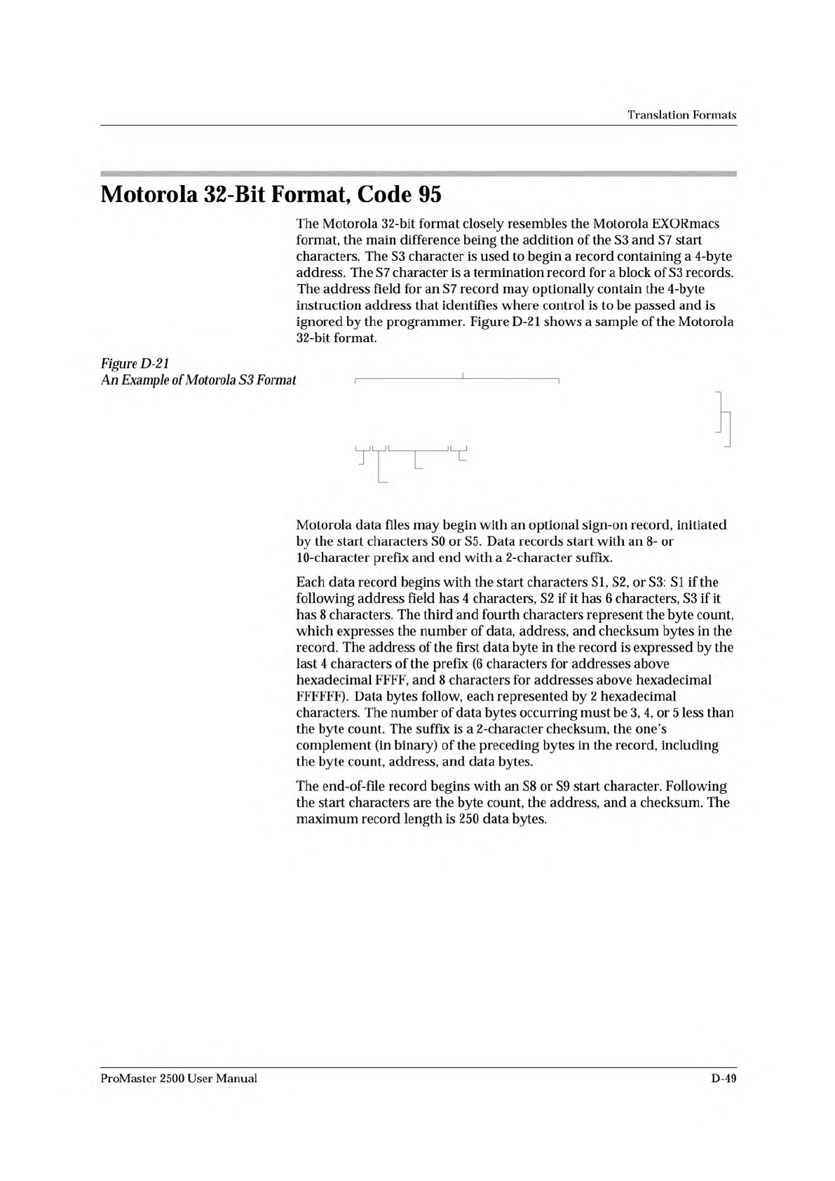
Start
Character
Byte Count
Address
Checksum
Optional Sign-On Record
Data
Records
0093-3
Translation
Formats
Motorola
32-Bit
Format,
Code
95
The
Motorola
32-bit
format
closely
resembles
the
Motorola
EXORmacs
format,
the
main
difference
being
the
addition
of
the
S3
and
S7
start
characters.
The
S3
character
is
used
to
begin
a
record
containing
a
4
-byte
address.
The
S7
character
is
a
termination
record
for
a
block
of
S3
records.
The
address
field
for
an
S7
record
may
optionally
contain
the
4-byte
instruction
address
that
identifies
where
control
is
to
be
passed
and
is
ignored
by
the
programmer.
Figure
D-21
shows
a
sample
of
the
Motorola
32-bit
format.
Figure
D-21
An
Example
of
Motorola
S3
Format
।
1
1
।
L
Motorola
data
files
may
begin
with
an
optional
sign-on
record,
initiated
by
the
start
characters
SO
or
S5.
Data
records
start
with
an
8-
or
1
O-character
prefix
and
end
with
a
2-character
suffix.
Each
data
record
begins
with
the
start
characters
SI,
S2,
or
S3:
SI
if
the
following
address
field
has
4
characters,
S2
if
it
has
6
characters,
S3
if
it
has
8
characters.
The
third
and
fourth
characters
represent
the
byte
count,
which
expresses
the
number
of
data,
address,
and
checksum
bytes
in
the
record.
The
address
of
the
first
data
byte
in
the
record
is
expressed
by
the
last
4
characters
of
the
prefix
(6
characters
for
addresses
above
hexadecimal
FFFF,
and
8
characters
for
addresses
above
hexadecimal
FFFFFF).
Data
bytes
follow,
each
represented
by
2
hexadecimal
characters.
The
number
of
data
bytes
occurring
must
be
3,
4,
or
5
less
than
the
byte
count.
The
suffix
is
a
2-character
checksum,
the
one's
complement
(in
binary)
of
the
preceding
bytes
in
the
record,
including
the
byte
count,
address,
and
data
bytes.
The
end-of-file
record
begins
with
an
S8
or
S9
start
character.
Following
the
start
characters
are
the
byte
count,
the
address,
and
a
checksum.
The
maximum
record
length
is
250
data
bytes.
ProMaster
2500
User
Manual
D-49
Translation
Formats
Hewlett-Packard
UNIX
Format,
Code
96
This
format
divides
the
data
file
into
data
records,
each
with
a
maximum
size
of
250
bytes
not
including
header
information.
An
ID
header
is
added
to
the
beginning
of
the
first
record.
Each
subsequent
record
has
its
own
header
section.
The
section
at
the
beginning
of
the
file
contains
the
following
elements:
the
header
8004,
filename,
byte
count
for
the
processor
information
record,
and
the
processor
information
record.
The
header
8004
identifies
the
type
of
file
being
transferred.
The
first
byte
of
this
header
(80)
indicates
that
this
file
is
binary,
and
the
04
indicates
the
type
of
file
(absolute).
The
ID
header
is
followed
by
a
16-byte
filename
(not
used
by
the
programmer).
Next
is
the
byte
count,
which
indicates
the
size
(minus
one)
of
the
Processor
Information
Record
that
follows.
The
Processor
Information
Record
is
divided
into
the
following
data
words:
Data
Bus
Width,
Data
Width
Base,
Transfer
Address
LS
(least
significant),
and
Transfer
Address
MS
(most
significant).
The
Data
Bus
Width
represents
the
width
of
the
target
system's
bus
(in
bits).
The
Data
Width
Base
represents
the
smallest
addressable
entity
used
by
the
target
microprocessor.
The
Data
Bus
Width
and
Data
Width
Base
are
not
used
by
the
programmer
during
download.
During
upload,
the
Data
Bus
Width
will
be
set
to
the
current
Data
Word
Width,
and
the
Data
Width
Base
will
be
set
to
8.
The
Transfer
Address
LS
and
Transfer
Address
MS
are
not
used
by
the
programmer.
The
data
records
consist
of
a
header
(8
bytes)
and
the
data
bytes.
The
first
2
bytes
of
the
header
indicate
the
size
of
the
data
record
including
the
header
(minus
one).
If
the
number
of
data
bytes
in
the
data
record
(not
including
the
header)
is
odd,
one
extra
byte
will
be
added
to
the
data
record
to
ensure
that
an
even
number
of
data
bytes
exist
in
the
data
record.
The
maximum
value
for
this
field
is
00FF
hex.
The
next
two
bytes
indicate
the
number
of
actual
data
bytes
in
the
record,
not
including
the
header
bytes
and
the
extra
byte
(if
present).
The
maximum
value
for
this
field
is
00FA
hex.
The
4
bytes
that
follow
represent
the
destination
address
for
the
data
in
this
record.
The
rest
of
the
bytes
in
the
record
are
the
data
bytes.
This
format
has
no
end
of
file
identifier.
D-50
ProMaster
2500
User
Manual