2500_Users_Manual-.pdf - 第256页
1649-1 CONFIGURATION BLOCK CONFIGURATION CONNECTOR CONTACT SET (1 of 4) 2 0 A 1 X 4 X BLOCK ALIGNMENT PIN (1 of 2) PROGRAMMING BLOCK ASSEMBLY CIRCUIT BOARD SCREW HOLE (1 of 2) CONFIGURATION CONNECTOR (1 of 4) 1669-2 Repa…
1929-1
CONTACT SET
RETAINING BLOCK (1 of 2)
SCREW (2 per side)
VIEW FROM BELOW
CROSS SECTION
CROSS SECTION PLANE
TILT CONTACT SET BEFORE
REMOVING OR INSERTING
Repair
and
Replacement
Procedures
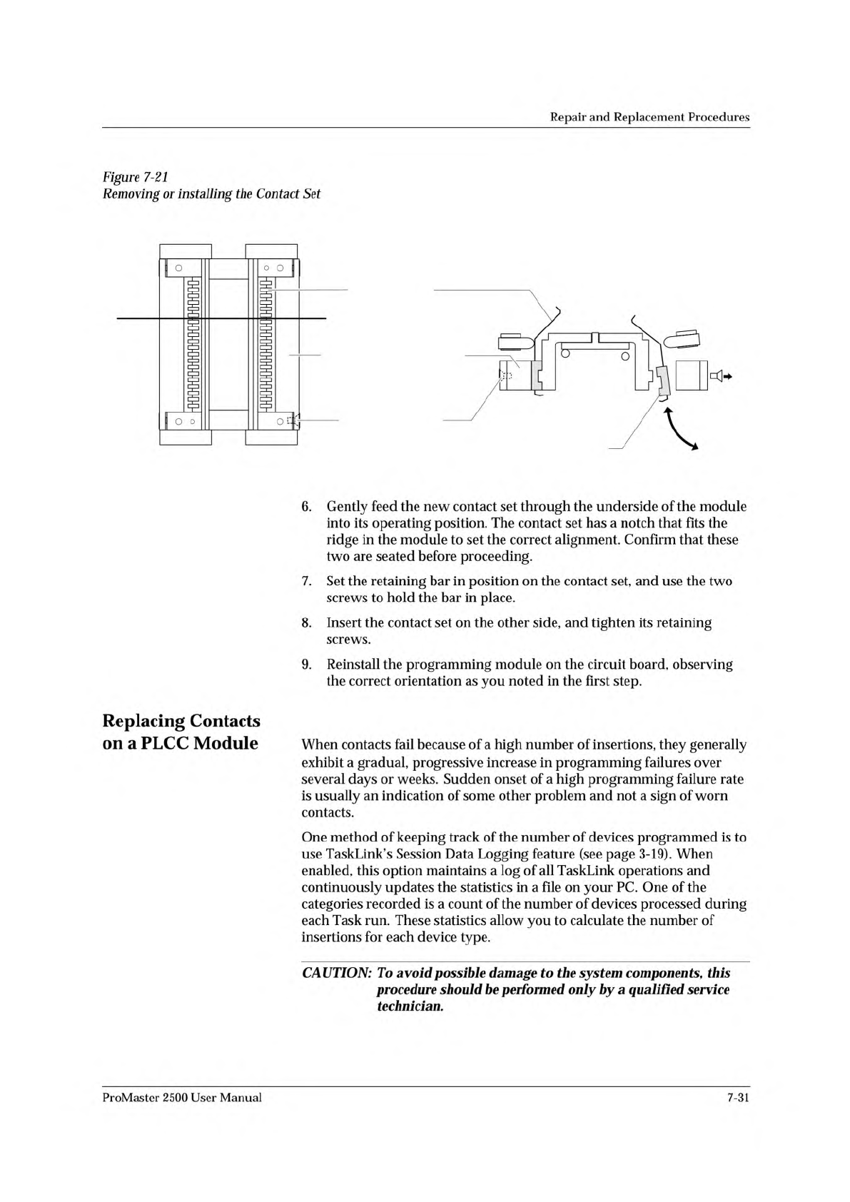
Figure
7-21
Removing
or
installing
the
Contact
Set
Replacing
Contacts
on
a
PLCC
Module
6.
Gently
feed
the
new
contact
set
through
the
underside
of
the
module
into
its
operating
position.
The
contact
set
has
a
notch
that
fits
the
ridge
in
the
module
to
set
the
correct
alignment.
Confirm
that
these
two
are
seated
before
proceeding.
7.
Set
the
retaining
bar
in
position
on
the
contact
set,
and
use
the
two
screws
to
hold
the
bar
in
place.
8.
Insert
the
contact
set
on
the
other
side,
and
tighten
its
retaining
screws.
9.
Reinstall
the
programming
module
on
the
circuit
board,
observing
the
correct
orientation
as
you
noted
in
the
first
step.
When
contacts
fail
because
of
a
high
number
of
insertions,
they
generally
exhibit
a
gradual,
progressive
increase
in
programming
failures
over
several
days
or
weeks.
Sudden
onset
of
a
high
programming
failure
rate
is
usually
an
indication
of
some
other
problem
and
not
a
sign
of
worn
contacts.
One
method
of
keeping
track
of
the
number
of
devices
programmed
is
to
use
TaskLink's
Session
Data
Logging
feature
(see
page
3-19).
When
enabled,
this
option
maintains
a
log
of
all
TaskLink
operations
and
continuously
updates
the
statistics
in
a
file
on
your
PC.
One
of
the
categories
recorded
is
a
count
of
the
number
of
devices
processed
during
each
Task
run.
These
statistics
allow
you
to
calculate
the
number
of
insertions
for
each
device
type.
CAUTION:
To
avoid
possible
damage
to
the
system
components,
this
procedure
should
加
performed
only
by
a
qualified
service
technician.
o
I
—Bo.
o
ProMaster
2500
User
Manual
7-31
1649-1
CONFIGURATION BLOCK
CONFIGURATION CONNECTOR
CONTACT SET
(1 of 4)
2
0
A
1
X
4
X
BLOCK ALIGNMENT
PIN (1 of 2)
PROGRAMMING
BLOCK ASSEMBLY
CIRCUIT BOARD
SCREW HOLE (1 of 2)
CONFIGURATION
CONNECTOR (1 of 4)
1669-2
Repair
and
Replacement
Procedures
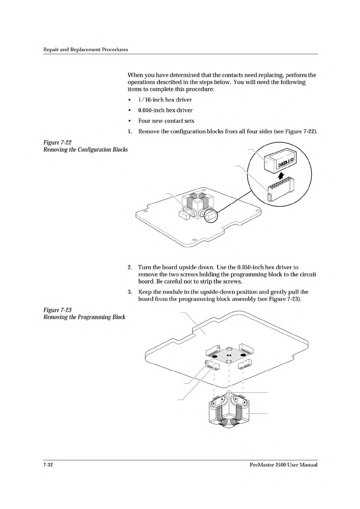
Figure
7-22
Removing
the
Configuration
Blocks
Figure
7-23
Removing
the
Programming
Block
When
you
have
determined
that
the
contacts
need
replacing,
perform
the
operations
described
in
the
steps
below.
You
will
need
the
following
items
to
complete
this
procedure:
•
1/16-inch
hex
driver
•
0.050-inch
hex
driver
•
Four
new
contact
sets
1.
Remove
the
configuration
blocks
from
all
four
sides
(see
Figure
7-22).
2.
Turn
the
board
upside
down.
Use
the
0.050-inch
hex
driver
to
remove
the
two
screws
holding
the
programming
block
to
the
circuit
board.
Be
careful
not
to
strip
the
screws.
3.
Keep
the
module
in
the
upside-down
position
and
gently
pull
the
board
from
the
programming
block
assembly
(see
Figure
7-23).
7-32
ProMaster
2500
User
Manual
1681-2
DEVICE EJECTOR PIN
DEVICE EJECTOR SPRING
PROGRAMMING
BLOCK ASSEMBLY
GOLD PIN
1668-1
CONTACT SET
PROGRAMMING BLOCK
ASSEMBLY
SCREW (1 of 2
per Contact Set)
Repair
and
Replacement
Procedures
4.
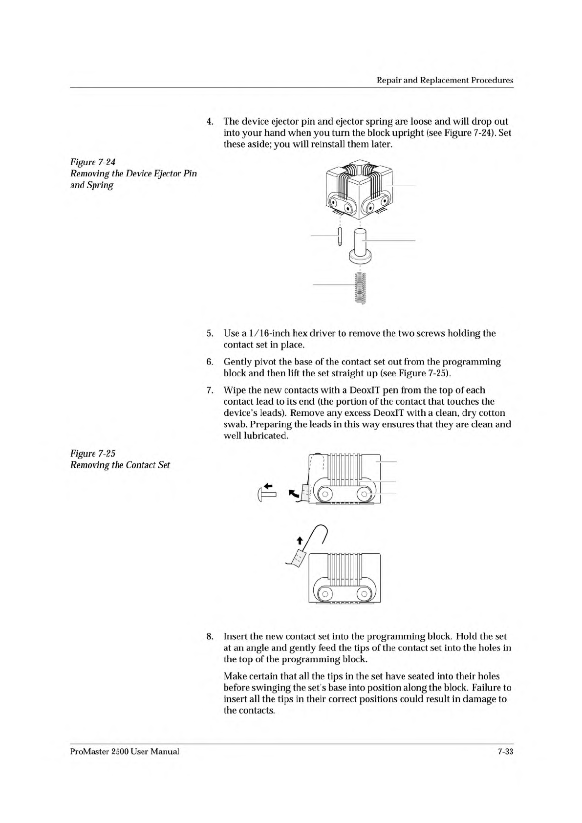
Figure
7-24
Removing
the
Device
Ejector
Pin
and
Spring
5.
6.
7.
Figure
7-25
Removing
the
Contact
Set
The
device
ejector
pin
and
ejector
spring
are
loose
and
will
drop
out
into
your
hand
when
you
turn
the
block
upright
(see
Figure
7-24).
Set
these
aside;
you
will
reinstall
them
later.
Use
a
1/16-inch
hex
driver
to
remove
the
two
screws
holding
the
contact
set
in
place.
Gently
pivot
the
base
of
the
contact
set
out
from
the
programming
block
and
then
lift
the
set
straight
up
(see
Figure
7-25).
Wipe
the
new
contacts
with
a
DeoxIT
pen
from
the
top
of
each
contact
lead
to
its
end
(the
portion
of
the
contact
that
touches
the
device's
leads).
Remove
any
excess
DeoxIT
with
a
clean,
dry
cotton
swab.
Preparing
the
leads
in
this
way
ensures
that
they
are
clean
and
well
lubricated.
8.
Insert
the
new
contact
set
into
the
programming
block.
Hold
the
set
at
an
angle
and
gently
feed
the
tips
of
the
contact
set
into
the
holes
in
the
top
of
the
programming
block.
Make
certain
that
all
the
tips
in
the
set
have
seated
into
their
holes
before
swinging
the
set's
base
into
position
along
the
block.
Failure
to
insert
all
the
tips
in
their
correct
positions
could
result
in
damage
to
the
contacts.
ProMaster
2500
User
Manual
7-33