2500_Users_Manual-.pdf - 第84页
< More > ↵ Handling/ Labeling Parameter s... ↵ Pa ckage ↵ Pin 1 Orientati on Tasks and Kits • Label — Select this parameter to label the devices. Devices do not have to be programmed (or verified) and labeled in th…
Tasks
and
Kits
The
value
of
YYYY YYYY
is
the
address
where
the
byte
of
data
is
stored
in
the
2500's
RAM.
Relative
Addressing
Under
most
circumstances
the
I/O
Offset
is
left
at
its
default
value
of
FFFFFFFF.
By
default,
the
2500
assumes
that
the
first
byte
of
data
it
receives
should
be
located
at
RAM
address
0
and
all
other
data
bytes
received
will
be
located
in
RAM
at
addresses
relative
to
the
address
of
the
first
byte.
During
a
data
file
download
from
the
PC
to
the
2500,
the
default
value
instructs
the
2500
to
take
the
first
data
byte
in
the
file
(regardless
of
the
address
that
byte
has
in
the
file)
and
save
it
at
the
2500's
RAM
address
=
0.
The
address
of
the
first
byte
becomes
the
I/O
Offset
value
and
is
subtracted
from
all
subsequent
data
file
addresses
to
arrive
at
the
ultimate
2500
RAM
address
for
that
file
data
byte.
The
sample
below
shows
how
this
relative
addressing
works
in
a
typical
application.
File
Download:
File
address
number
800
-
I/O
offset
number
-800
XXXXXXXX
000
+
Begin
RAM
number
+000
2500
RAM
address
=
YYYY
YYYY
000
Absolute
Addressing
This
parameter
is
usually
changed
from
the
default
during
a
file
download
from
the
PC
to
2500's
RAM.
Some
file
formats
(primarily
the
Intel
formats)
use
absolute
addresses.
In
this
context
we
mean
that
the
address
of
each
data
byte
in
the
file
is
the
absolute
address
and
the
data
byte
associated
with
that
address
should
be
saved
at
the
same
address
in
the
2500's
RAM.
If
your
file
uses
absolute
addressing,
then
the
I/O
Offset
should
be
set
to
0.
The
following
example
shows
how
this
absolute
addressing
works
in
a
typical
application.
File
Download:
File
address
number
800
-
I/O
offset
number
-
000
XXXX
XXXX
800
+
Begin
RAM
number
+
000
2500
RAM
address
=
YYYY YYYY
800
If
you
have
a
file
with
absolute
addressing
and
the
programmer
is
using
the
default
(relative
addressing),
the
file
will
download
and
the
devices
will
program
without
any
error
messages.
However,
the
devices
will
not
be
programmed
correctly,
because
the
RAM
was
not
loaded
with
data
at
the
intended
locations.
ProMaster
2500
User
Manual
3-17
< More >
↵
Handling/
Labeling Parameters...
↵
Package
↵
Pin 1 Orientation
Tasks
and
Kits
•
Label
—
Select
this
parameter
to
label
the
devices.
Devices
do
not
have
to
be
programmed
(or
verified)
and
labeled
in
the
same
process.
They
can
be
programmed
and
placed
in
tubes
to
be
labeled
by
the
2500
later.
The
2500
default
configuration
will
not
label
devices
that
have
failed
the
programming
operation.
(The
2500
can
be
configured
to
label
both
passed
and
failed
devices.
Refer
to
the
Binning
command
in
local
mode
in
Appendix
F.)
Devices
that
have
failed
can
be
labeled
only
by
passing
them
through
the
2500
a
second
time.
Selecting
Handling/
Labeling
Parameters
Numerous
parameters
are
available
by
selecting
the
pushbutton.
Press
and
the
More
Task
Parameters
selection
box
appears
(see
Figure
3-1,
screen
4).
Most
of
these
should
remain
at
their
default
settings.
The
parameters
that
must
be
defined
for
all
Tasks
are
the
selections.
Move
the
screen
cursor
over
Handling/Labeling
Parameters...
and
press
to
select
this
parameter
set.
The
following
handler
and
labeler
parameters
are
defined
in
this
dialog
box.
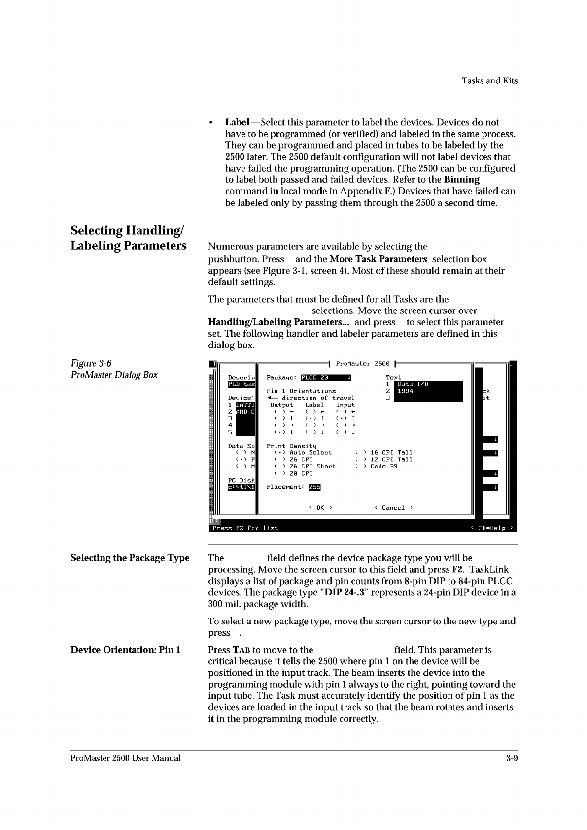
Figure
3-6
ProMaster
Dialog
Box
ProMaster
Z500
Package:
Text
Dev
ice(
<
OK
> <
Cancel
>
IPLCC
Z0
Press
FZ
For
list
Fl=Help
>
LATTI
AMD
C
Tall
Tall
1
Z
3
1
Z
3
4
5
16
CPI
'
1Z
CPI
'
Code
39
Data
I/O
1994
Descrip
PC
Disk
Input
( )
( )
t
Data
So
( )
N
( )
P
( )
M
Pin
1
Orientations
<
—
direction
of
travel
Print
Density
(
)
Auto
Select
( )
Z6
CPI
(
)
Z6
CPI
Short
(
)
Z0
CPI
Output
Label
( )
~
(
)
?
(
•
)
?
Selecting
the
Package
Type
The
field
defines
the
device
package
type
you
will
be
processing.
Move
the
screen
cursor
to
this
field
and
press
F2.
TaskLink
displays
a
list
of
package
and
pin
counts
from
8-pin
DIP
to
84-pin
PLCC
devices.
The
package
type
“DIP
24-.3"
represents
a
24-pin
DIP
device
in
a
300
mil.
package
width.
To
select
a
new
package
type,
move
the
screen
cursor
to
the
new
type
and
press
.
Device
Orientation:
Pin
1
Press
Tab
to
move
to
the
field.
This
parameter
is
critical
because
it
tells
the
2500
where
pin
1
on
the
device
will
be
positioned
in
the
input
track.
The
beam
inserts
the
device
into
the
programming
module
with
pin
1
always
to
the
right,
pointing
toward
the
input
tube.
The
Task
must
accurately
identify
the
position
of
pin
1
as
the
devices
are
loaded
in
the
input
track
so
that
the
beam
rotates
and
inserts
it
in
the
programming
module
correctly.
ProMaster
2500
User
Manual
3-9
Tasks
and
Kits
Serializing
Devices
You
may
want
to
program
a
serial
number
into
the
devices
and/or
print
the
number
on
the
label.
TaskLink's
Serialization...
option
offers
an
opportunity
to
do
this
in
software.
A
sample
serialization
program
called
serializ.exe
is
provided
with
TaskLink.
For
detailed
information
on
the
serialization
program,
refer
to
the
External
Serialization
Program
section
on
page
3-25
and
to
the
online
help
topic
“Writing
a
Serialization
Program”
under
TaskLink's
General
Help
Index.
To
implement
serialization
features
not
provided
by
serializ.exe,
you
will
need
to
write
a
short
external
serialization
program
(ESP)
to
generate
your
serial
number
and
save
it
in
an
ASCII
file
for
TaskLink
to
use.
To
print
a
serial
number
on
a
label,
enter
a
percent
sign
(%)
in
the
label
text
field
(ProMaster
2500
dialog
box)
for
each
character
to
be
printed
on
the
label
(refer
to
the
command
line
length
parameter
Note:
You
must
have
UI
5
version
1.06
or
greater
to
print
a
serial
number.
Figure
3-16
shows
the
process
steps
in
creating
a
file
to
be
used
for
serializing
devices.
The
Program
line
in
TaskLink's
Serialization
Parameters
screen
(see
Figure
3-15)
allows
you
to
enter
the
executable
name
for
your
external
program
(ESP).
You
can
also
include
the
path
and
command
line
arguments
that
define
the
characteristics
of
the
serial
number
to
pass
to
the
ESP.
The
ESP
is
called
from
the
command
line
using
a
command
similar
to
the
following:
drive:
\
path
\file_name
where
drive
is
the
drive
where
the
ESP
resides,
path
is
a
valid
DOS
path
to
the
subdirectory
where
the
ESP
is
written,
and
flle_name
is
the
ESP
executable
file
name
and
extension.
3-22
ProMaster
2500
User
Manual