2500_Users_Manual-.pdf - 第151页
MAIN PLATE (Underside) BACK OF BASE BOTTOM OF BASE FRONT OF BASE LABEL ADVANCE MOTOR PRINT HEAD P2 AC IN P1 TB2 TB1 J1 J2 J3 J4 240 220 120 100 J27 J22 J23 J24 J25 J24 J25 J3 J9 J10 J12 J1 3 J2 J11 * DISK DRIVE AC IN CON…
Preventive
Maintenance
The
Controller
Board
The
components
of
the
controller
board
are
listed
below.
•
LEDs
—
Used
for
a
quick
visual
check
on
the
status
of
various
power
supplies,
solenoids,
and
certain
logic
signals.
•
Connectors
—
Route
control
signals
to
optics,
microswitch,
motors,
solenoids,
and
other
components
of
the
handler.
•
Pico
fuses
—
12
for
the
stepper
motors
(two
per
stepper
driver
circuit
and
four
for
the
traverse
motor)
and
24
for
the
dot
matrix
print
head
wires
(one
fuse
for
each
wire
in
the
print
head).
Refer
to
the
schematic
in
Appendix
C
for
the
location
of
the
pico
fuses
associated
with
each
motor.
The
components
of
the
controller
board
supply
the
following:
•
Signals
to
activate
the
solenoids,
the
motors,
and
the
labeler
wires
•
Control
signals
for
the
two
RS-
232c
ports
and
the
handler
port
•
EPROM
that
contains
the
handler
system
firmware
•
EEPROM
that
stores
nonvolatile
handler
parameters
•
Circuitry
for
the
optics,
the
display,
and
the
keyboard
•
Microprocessor
and
kernel
logic
control
Refer
to
Appendix
C
for
the
controller
board
schematic
and
layout.
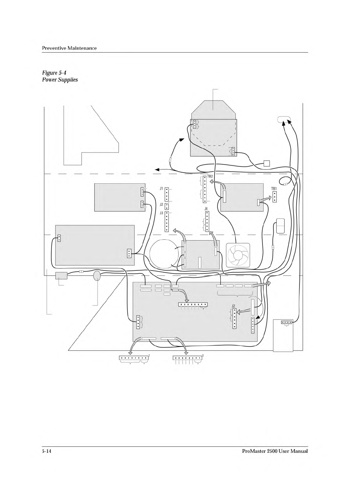
Power
Supplies
Four
power
supply
assemblies
are
located
in
the
body
of
the
2500.
See
Figure
5-4.
These
supplies
operate
off
the
handler's
single
AC
input.
•
Programming
Electronics
(PE)
Power
Supply:
PE
Controller/
Waveform
board
(+15V).
•
Labeler
Power
Supply:
Print
head
(+24V)
/solenoids
•
Toroid
Power
Supply:
•
Label
advance
motor
(+36V)
•
Input
orbital
motor
(+36V)
•
Output
orbital
motor
(+36V)
•
Beam
head
rotation
motor
(+36V)
•
Beam
traverse
motor
(+90V)
•
Controller
Board
Power
Supply:
Logic,
vacuum
generators,
sensor,
optics,
RS-
232c
ports,
and
the
2500's
display
(5V,
+/-12V).
ProMaster
2500
User
Manual
5-13
MAIN PLATE (Underside)
BACK OF BASE
BOTTOM OF BASE
FRONT OF BASE
LABEL
ADVANCE
MOTOR
PRINT HEAD
P2
AC IN P1
TB2
TB1
J1
J2
J3
J4
240
220
120
100
J27
J22
J23
J24 J25
J24 J25
J3
J9 J10 J12 J13
J2
J11
*
DISK
DRIVE
AC
IN
CONTROLLER
BOARD
POWER
SUPPLY
PROGRAMMING
ELECTRONICS
POWER SUPPLY
(TO BEAM)
SOLENOID
CLAMP
(TO SOLENOIDS
2 AND 3)
CONTROLLER
BOARD
PROGRAMMING ELECTRONICS
CONTROLLER BOARD
(TO BEAM
TRAVERSE
MOTOR)
MOTORS
**
* +90V on all six pins while motor is inactive.
** Approx. 16Vac (rms) while motor is running.
FAN
TORROID
POWER
SUPPLY
LABELER
POWER SUPPLY
2055-3
1
1
120V
GND
AC IN
GND
+24V
V1
+24V
+24V GND
+24V
NC
1
NC
+5V
GND
+12V
NC
-12V
NC
0
24
0
24
24
24
NC
1
1
1
120Vac
120Vac
97Vac
1
+15V
NC
+90V
GND
+90V
+36V GND
+36V
GND
NC
GND
120
+90V
GND
+90V
+36V GND
+36V
J10 - BEAM
ROTATE
MOTOR
J12 - INPUT
ORBITAL
MOTOR
J13 - OUTPUT
ORBITAL
MOTOR
GND
+15V
NC
GND
+15V
GND
NC
+5V
Preventive
Maintenance
Figure
5-4
Power
Supplies
5-14
ProMaster
2500
User
Manual
↵
↵
↵
↵
↵
Operation
Running
a
Kit
Kits
operate
very
much
like
Tasks.
If
you
are
familiar
with
running
a
Task,
you
will
find
that
the
steps
required
to
run
a
Kit
are
almost
the
same.
The
process
of
running
a
Kit
is
outlined
in
the
steps
below.
Refer
to
Figure
4-31
to
see
the
TaskLink
screens
associated
with
these
steps.
1.
Select
a
Kit
from
the
Run
Task/Kit
list
box.
Kit
names
are
displayed
on
the
screen
with
bold
characters,
Tasks
appear
as
normal
characters.
2.
The
next
screen
asks
if
you
want
to
perform
all
the
Tasks
in
the
Kit
or
select
just
one
Task.
In
most
cases
you
will
perform
all
the
Tasks
in
the
Kit
(the
default
selection).
Press
to
run
the
entire
Kit.
3.
The
Process
Devices
dialog
box
appears,
prompting
you
for
the
number
of
Kits
to
Build
and
a
Session
LD.
Enter
the
number
of
devices
you
want
to
program
and
then
press
.
Note:
The
Session
LD.
is
an
arbitrary
string
of
printable
characters
that
will
appear
in
the
log
file
for
your
reference.
4.
You
will
now
see
the
normal
series
of
Task
dialog
boxes
appear.
Answer
these
as
you
do
when
running
a
single
Task.
5.
When
the
first
Task
has
successfully
programmed
the
number
of
devices
defined
in
the
Process
Devices
dialog
box,
a
programming
summary
screen
displays
the
results
for
the
Task
just
completed.
Press
to
go
on
to
the
second
Task
in
the
Kit.
6.
If
your
system
administrator
has
created
a
message
screen
with
special
instructions
for
the
next
Task,
that
screen
is
displayed.
Once
you
have
completed
these
steps,
press
and
TaskLink
will
begin
running
the
second
Task
in
the
Kit.
If
no
message
screen
has
been
created,
the
second
Task
started
running
when
you
pressed
in
step
5.
Note:
Remember
that
between
Tasks
in
the
Kit,
you
may
have
to
reconfigure
协
e
2500
for
a
new
device
package
type.
This
may
require
adjusting
the
track,
changing
labels,
changing
and/or
configuring
the
programming
module,
and
the
normal
steps
required
before
starting
any
new
Task.
7.
Continue
in
this
sequence
of
steps
until
the
last
Task
has
completed.
At
the
end
of
the
Kit's
run,
a
Kit
Processing
Results
screen
appears
with
a
summary
of
the
Kit
results.
4-38
ProMaster
2500
User
Manual