2500_Users_Manual-.pdf - 第350页
Translation Formats Although each data byte has an address, most are implied. Data bytes are addressed sequentially unless an explicit address is included in the data stream. This address is preceded by a $ and an A, mus…
Translation
Formats
JEDEC
Field
Syntax
<field>
::
=
[<delimiter>]<field
identifler>{<field
character〉}'*'
<field
identifier>::=
'A'
|
C
|
'D'
|
F
|
'G'
|
K
|
'L'
|
'N'
|
P
|
qTrTstttvtx,
〈
reserved
identifier>::=
'B'
|
E
|
'H'
|
T
|
'J'
|
'M'
「
0'
|
'U'
|
'W'
1
,y,
।
Z
Following
the
design
specification
field
in
a
JEDEC
transmission
can
be
any
number
of
information
fields.
Each
of
the
JEDEC
fields
begins
with
a
character
that
identifies
what
type
of
field
it
is.
Fields
are
terminated
with
an
asterisk
character.
Multiple
character
identifiers
can
be
used
to
create
sub-fields
(i.e.,
Al,
A$,
or
AB3).
Although
they
are
not
required,
you
may
use
carriage
returns
(CR)
and
line
feeds
(LF)
to
improve
readability
of
the
data.
Field
Identifiers
Field
identifiers
which
are
currently
used
in
JEDEC
transmissions
are
shown
above
on
the
“field
identifiers
n
line.
The
“reserved
identifier
M
line
indicates
characters
not
currently
used
(reserved
for
future
use
as
field
identifiers).
JEDEC
field
identifiers
are
defined
as
follows:
A
Access
time
N
Note
field
B
*
O
*
C
Checksum
field
P
Pin
sequence
D
Device
type
Q
Value
field
E
*
R
Resulting
vector
field
F
Default
fuse
state
field
S
Starting
vector
G
Security
fuse
field
T
Test
cycles
H
*
U
*
I
*
V
Test
vector
field
J
*
w
*
K
Fuse
list
field
(hex
format)
X
Default
test
condition
L
Fuse
list
field
Y
*
M
*
Z
*
Device
Field
(D)
*
Reserved
for
future
use
Device
selection
by
this
field
is
not
supported
by
the
programmer.
It
has
been
replaced
by
the
QF
and
QP
fields
and
manual
selection
of
devices.
ProMaster
2500
User
Manual
D-39
Translation
Formats
Although
each
data
byte
has
an
address,
most
are
implied.
Data
bytes
are
addressed
sequentially
unless
an
explicit
address
is
included
in
the
data
stream.
This
address
is
preceded
by
a
$
and
an
A,
must
contain
2
to
8
hex
or
3
to
11
octal
characters,
and
must
be
followed
by
a
comma,
except
for
the
ASCII-Hex
(Comma)
format,
which
uses
a
period.
The
programmer
skips
to
the
new
address
to
store
the
next
data
byte;
succeeding
bytes
are
again
stored
sequentially.
Each
format
has
an
end
code,
which
terminates
input
operations.
However,
if
a
new
start
code
follows
within
16
characters
of
an
end
code,
input
will
continue
uninterrupted.
If
no
characters
come
within
2
seconds,
input
operation
is
terminated.
After
receiving
the
final
end
code
following
an
input
operation,
the
programmer
calculates
a
sumcheck
of
all
incoming
data.
Optionally,
a
sumcheck
can
also
be
entered
in
the
input
data
stream.
The
programmer
compares
this
sumcheck
with
its
own
calculated
sumcheck.
If
they
match,
the
programmer
will
display
the
sumcheck;
if
not,
a
sumcheck
error
will
be
displayed.
Note:
The
sumcheck
field
consists
of
either
2-4
hex
or
3-6
octal
characters,
sandwiched
between
the
$
and
comma
characters.
The
sumcheck
immediately
follows
end
code.
The
sumcheck
is
optional
in
the
input
mode
but
is
always
included
in
the
output
mode.
The
most
significant
digit
of
the
sumcheck
may
be
0
or
1
when
expressing
1
6
bits
as
6
octal
characters.
The
programmer
divides
the
output
data
into
8-line
blocks.
Data
transmission
is
begun
with
the
start
code,
a
nonprintable
STX
character,
or
optionally,
SOH.*
Data
blocks
follow,
each
one
prefaced
by
an
address
for
the
first
data
byte
in
the
block.
The
end
of
transmission
is
signaled
by
the
end
code,
a
nonprintable
ETX
character.
Directly
following
the
end
code
is
a
sumcheck
of
the
transferred
data.
*
ASCII-Octal
SMS
and
ASCII-Hex
SMS
use
SOM
(CTRL-R)
as
a
start
code
and
EOM
(CTRL-T)
as
an
end
code.
D-20
ProMaster
2500
User
Manual
!M0000 ,
FFFFFFFFFFFFFFFFFFFFFFFFFFFFFFFF,
FFFFFFFFFFFFFFFFFFFFFFFFFFFFFFFF,
FFFFFFFFFFFFFFFFFFFFFFFFFFFFFFFF,
FFFFFFFFFFFFFFFFFFFFFFFFFFFFFFFF,
FFFFFFFFFFFFFFFFFFFFFFFFFFFFFFFF
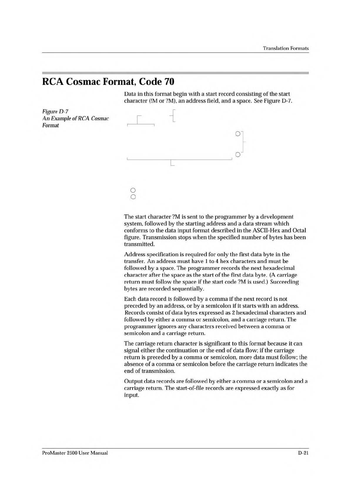
Start Record
!M or ?M = Start Characters
0000 = Address
End-of-File Record
1
2
Data Records
FF =
, =
; =
2 Hex Characters = (1 Byte)
Bytes per record is variable
End of Record Character
End of Record Character
if followed by expressed
address
LEGEND
Nonprinting line feed, carriage return, and nulls
Nonprinting carriage return
1
2
0079-2
Translation
Formats
RCA
Cosmac
Format,
Code
70
Data
in
this
format
begin
with
a
start
record
consisting
of
the
start
character
(!M
or
?M),
an
address
field,
and
a
space.
See
Figure
D-7.
Figure
D-7
An
Example
of
RCA
Cosmac
厂
Format
'
1
on
o
The
start
character
?M
is
sent
to
the
programmer
by
a
development
system,
followed
by
the
starting
address
and
a
data
stream
which
conforms
to
the
data
input
format
described
in
the
ASCII-Hex
and
Octal
figure.
Transmission
stops
when
the
specified
number
of
bytes
has
been
transmitted.
Address
specification
is
required
for
only
the
first
data
byte
in
the
transfer.
An
address
must
have
1
to
4
hex
characters
and
must
be
followed
by
a
space.
The
programmer
records
the
next
hexadecimal
character
after
the
space
as
the
start
of
the
first
data
byte.
(A
carriage
return
must
follow
the
space
if
the
start
code
?M
is
used.)
Succeeding
bytes
are
recorded
sequentially.
Each
data
record
is
followed
by
a
comma
if
the
next
record
is
not
preceded
by
an
address,
or
by
a
semicolon
if
it
starts
with
an
address.
Records
consist
of
data
bytes
expressed
as
2
hexadecimal
characters
and
followed
by
either
a
comma
or
semicolon,
and
a
carriage
return.
The
programmer
ignores
any
characters
received
between
a
comma
or
semicolon
and
a
carriage
return.
The
carriage
return
character
is
significant
to
this
format
because
it
can
signal
either
the
continuation
or
the
end
of
data
flow;
if
the
carriage
return
is
preceded
by
a
comma
or
semicolon,
more
data
must
follow;
the
absence
of
a
comma
or
semicolon
before
the
carriage
return
indicates
the
end
of
transmission.
Output
data
records
are
followed
by
either
a
comma
or
a
semicolon
and
a
carriage
return.
The
start-of-file
records
are
expressed
exactly
as
for
input.
ProMaster
2500
User
Manual
D-21