2500_Users_Manual-.pdf - 第150页
Preventive Maintenance The Controller Board The components of the controller board are listed below. • LEDs — Used for a quick visual check on the status of various power supplies, solenoids, and certain logic signals. •…
Preventive
Maintenance
High
Air
Pressure
Beam
Programming
Module
Clamp
Assembly
High
pressure
air
is
routed
from
the
high
pressure
regulator
to
a
Y
connection
and
is
divided
into
beam
high
pressure
and
programming
module
clamp
assembly
air
pressure.
The
beam
high
pressure
air
is
routed
to
the
beam
by
a
black
air
line
that
passes
through
the
beam
and
into
a
straight-in
air
fitting
on
the
back
right
side
of
the
beam.
This
air
passes
two
milled-in
air
caps
(cavities),
which
dampen
air
spikes,
and
goes
to
solenoids
6
and
7,
mounted
to
the
left
center
of
the
beam.
Creating
the
Beam
Vacuum
The
beam
vacuum
required
to
hold
a
device
on
the
chuck
is
created
when
solenoid
7
(vacuum)
is
activated.
The
high
pressure
air
passes
through
the
beam
passes
through
the
top
hole
of
the
vacuum
venturi,
and
escapes
through
holes
in
the
bottom
of
the
beam.
As
this
rush
of
air
passes
the
venturi,
it
creates
a
vacuum
at
the
chuck
tip.
During
the
optics
test,
the
vacuum
value
should
fluctuate
between
about
26
(when
no
device
is
on
the
chuck)
and
172,
with
a
value
of
140
minimum
for
proper
vacuum.
The
vacuum
is
sensed
by
the
vacuum
sensor
(mounted
at
the
left
front
of
the
beam).
When
a
predefined
vacuum
level
is
detected
by
a
device
blocking
the
chuck
tip,
the
2500
assumes
that
the
beam
has
picked
up
a
device.
A
malfunction
of
the
vacuum
generator,
the
vacuum
sensor,
or
the
microswitch
can
cause
an
error
message
on
the
2500's
display
stating
that
the
beam
has
dropped
the
device
or
is
unable
to
pick
up
the
device.
Inserting
a
Device
into
the
Module
Low
pressure
air
lowers
the
beam
to
the
programming
module
contacts.
Additional
force
is
required
to
insert
the
device
into
the
programming
module.
Insertion
begins
when
the
high
pressure
air
present
at
hole
4
is
switched
to
hole
5
by
beam
solenoid
6
(high
pressure).
This
high
pressure
passes
to
hole
21,
pushing
the
ball
bearing
down
and
sealing
off
the
low
pressure
of
hole
19.
This
allows
high
pressure
to
pass
to
hole
20
and
enter
the
bottom
of
the
cylinder
at
hole
18.
Air
pushing
against
the
fixed
piston
pushes
the
beam
down
to
establish
the
required
continuity
between
the
devices
leads
and
the
module's
contacts.
Programming
module
clamp
assembly
air
is
switched
by
solenoid
8
to
either
open
the
clamps
(to
remove
a
module)
or
close
the
clamps
(to
hold
a
module
in
place).
Red
air
lines
carry
air
to
close
the
clamps;
blue
air
lines
carry
air
to
open
the
clamps.
In-line
valves
on
these
lines
control
the
amount
of
air
entering
the
air
cylinders
and
allow
ac^ustment
so
each
side
of
the
clamp
opens
and
closes
at
the
same
rate.
The
in-line
valves
for
the
red
lines
are
in
the
middle
of
the
air
lines,
while
the
valves
for
the
blue
lines
are
at
the
base
of
each
air
cylinder.
5-12
ProMaster
2500
User
Manual
Preventive
Maintenance
The
Controller
Board
The
components
of
the
controller
board
are
listed
below.
•
LEDs
—
Used
for
a
quick
visual
check
on
the
status
of
various
power
supplies,
solenoids,
and
certain
logic
signals.
•
Connectors
—
Route
control
signals
to
optics,
microswitch,
motors,
solenoids,
and
other
components
of
the
handler.
•
Pico
fuses
—
12
for
the
stepper
motors
(two
per
stepper
driver
circuit
and
four
for
the
traverse
motor)
and
24
for
the
dot
matrix
print
head
wires
(one
fuse
for
each
wire
in
the
print
head).
Refer
to
the
schematic
in
Appendix
C
for
the
location
of
the
pico
fuses
associated
with
each
motor.
The
components
of
the
controller
board
supply
the
following:
•
Signals
to
activate
the
solenoids,
the
motors,
and
the
labeler
wires
•
Control
signals
for
the
two
RS-
232c
ports
and
the
handler
port
•
EPROM
that
contains
the
handler
system
firmware
•
EEPROM
that
stores
nonvolatile
handler
parameters
•
Circuitry
for
the
optics,
the
display,
and
the
keyboard
•
Microprocessor
and
kernel
logic
control
Refer
to
Appendix
C
for
the
controller
board
schematic
and
layout.
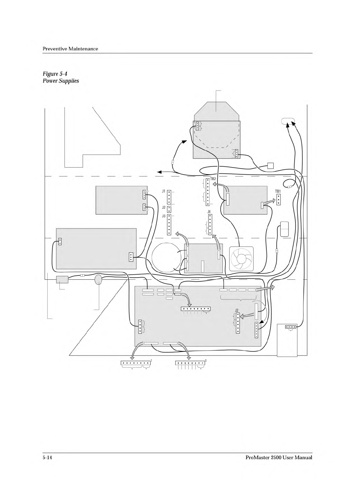
Power
Supplies
Four
power
supply
assemblies
are
located
in
the
body
of
the
2500.
See
Figure
5-4.
These
supplies
operate
off
the
handler's
single
AC
input.
•
Programming
Electronics
(PE)
Power
Supply:
PE
Controller/
Waveform
board
(+15V).
•
Labeler
Power
Supply:
Print
head
(+24V)
/solenoids
•
Toroid
Power
Supply:
•
Label
advance
motor
(+36V)
•
Input
orbital
motor
(+36V)
•
Output
orbital
motor
(+36V)
•
Beam
head
rotation
motor
(+36V)
•
Beam
traverse
motor
(+90V)
•
Controller
Board
Power
Supply:
Logic,
vacuum
generators,
sensor,
optics,
RS-
232c
ports,
and
the
2500's
display
(5V,
+/-12V).
ProMaster
2500
User
Manual
5-13
MAIN PLATE (Underside)
BACK OF BASE
BOTTOM OF BASE
FRONT OF BASE
LABEL
ADVANCE
MOTOR
PRINT HEAD
P2
AC IN P1
TB2
TB1
J1
J2
J3
J4
240
220
120
100
J27
J22
J23
J24 J25
J24 J25
J3
J9 J10 J12 J13
J2
J11
*
DISK
DRIVE
AC
IN
CONTROLLER
BOARD
POWER
SUPPLY
PROGRAMMING
ELECTRONICS
POWER SUPPLY
(TO BEAM)
SOLENOID
CLAMP
(TO SOLENOIDS
2 AND 3)
CONTROLLER
BOARD
PROGRAMMING ELECTRONICS
CONTROLLER BOARD
(TO BEAM
TRAVERSE
MOTOR)
MOTORS
**
* +90V on all six pins while motor is inactive.
** Approx. 16Vac (rms) while motor is running.
FAN
TORROID
POWER
SUPPLY
LABELER
POWER SUPPLY
2055-3
1
1
120V
GND
AC IN
GND
+24V
V1
+24V
+24V GND
+24V
NC
1
NC
+5V
GND
+12V
NC
-12V
NC
0
24
0
24
24
24
NC
1
1
1
120Vac
120Vac
97Vac
1
+15V
NC
+90V
GND
+90V
+36V GND
+36V
GND
NC
GND
120
+90V
GND
+90V
+36V GND
+36V
J10 - BEAM
ROTATE
MOTOR
J12 - INPUT
ORBITAL
MOTOR
J13 - OUTPUT
ORBITAL
MOTOR
GND
+15V
NC
GND
+15V
GND
NC
+5V
Preventive
Maintenance
Figure
5-4
Power
Supplies
5-14
ProMaster
2500
User
Manual